Audio Amplifier Circuit – 15 Watts
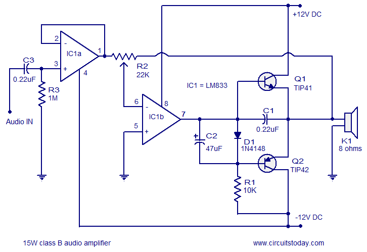
The circuit below is of a 15 Watts Class B audio amplifier circuit designed using a dual Op-amp and transistors.
Description :
The circuit shown here is of a simple Class-B audio amplifier based on opamp TL082, transistors TIP41 and TIP42. LM833 is a dual opamp with high slew rate and low distortion particularly designed for audio applications. This audio amplifier circuit can deliver 15 watt audio output into an 8 ohm speaker at +12/-12V DC dual supply.
Both opamps in the IC are used here. IC1a is wired as a buffer and capacitor C3 does the job of input DC decoupling. Ic1b is wired in the inverting mode and it provides negative feedback. Complementary power transistors TIP41 and TIP42 are wired in the Class B push pull scheme and they drives the loud speaker. Diode D1 provides 0.7V bias voltage for the push pull pair and capacitor C2 protects the 0.7V bias voltage across D1 from heavy voltage swings at the IC1b’s output.
Circuit diagram of Audio amplifier-15W
Notes :
- The audio amplifier circuit must be assembled on a good quality PCB.
- Use a holder for mounting IC1.
- Use a +12/-12V dual supply for powering the amplifier.
- Potentiometer R2 can be used as a volume control.
- Raising the power supply voltage will increase the output power. Anyway note the following points.
- TIP42 and 41 can handle only up to 6A.
- Maximum supply voltage IC1 can handle is +16/-16 V DC.
Some other popular Audio Amplifier circuits on this website:
2. 20 Watt Audio Amplifier Circuit
3. Motional Feedback Amplifier
4. Car Stereo Amplifier Circuit


7 Comments
hi, i cannot get this to work, i have been through the schematic over and over again and cannot find the problem. When i run 12v trough it, Q1 heats up but Q2 doesn’t and neither do the IC’s, im just trying to play my iPhone through it, any ideas?
can i connect another output transistor in parallel to obtain a more powerful output?………,,,,,,,
hi, i already built dis circuit, but instead of lm833 i use lm2902n quad op amp with +/-26v w/o a PCB and its work great!!!…..,
How do you get 15W out of this, by my calcs it is only about 9 (assuming 20V allowed peak to peak swing, 7V rms over 8 ohm load?
Thanks
Hi, I am doing a project using a speaker, 8ohms,120W rms, as a weight scale. My input is not Audio input as above, but 0 up to +15DCV. Can I use the same configuration and still have an output power of 15watts? Does it mean I will only be using the TP41 transitor only, “positive half cycle”?
Hi Jonathan with Darling ton transistors it is better to use minimum 2diodes in bias D1 + D2 to avoid cross over distortion at very low volumes if out put transistors are not really matched for current gain.
The outputs are listed as TIP141/142 in the description, but
TIP41/42 in schematic. The 141/142s are the desired parts.