LM4910 stereo headphone amplifier.
LM4910 belonging to the Boomer series of National Semiconductors is an integrated stereo amplifier primarily intended for stereo headphone applications. The IC can be operated from 3.3V ans its can deliver 0.35mW output power into a 32 ohm load. The LM4910 has very low distortion ( less than 1%) and the shutdown current is less than 1uA. This low shut down current makes it suitable for battery operated applications. The IC is so designed that there is no need of the output coupling capacitors, half supply by-pass capacitors and bootstrap capacitors. Other features of the IC are turn ON/OFF click elimination, externally programmable gain etc.
Circuit diagram.

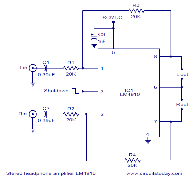
Circuit diagram of the LM4910 stereo headphone amplifier is shown above.C1 and C2 are the input DC decoupling capacitors for the left and right input channels. R1 and R2 are the respective input resistors. R3 is the feed back resistor for left channel while R4 is the feed back resistor for the right channel. C3 is the power supply filter capacitor. The feedback resistors also sets the closed loop gain in conjunction with the corresponding input resistors.
Notes.
- The IC is available only in SMD packages and care must be taken while soldering.
- The circuit can be powered from anything between 2.2V to 5V DC.
- The load can be a 32 ohm headphone.
- Absolute maximum supply voltage is 6V and anything above it will destroy the IC.
- A logic low voltage at the shutdown pins shut downs the IC and a logic high voltage at the same pin activates the IC.

8 Comments
Please give me equation for the gain, in comments. I can’t find the data sheet in pdf and how to know that it is dependable. Please help.
Hi Baas R3/R1 & R4/R2 sets the gain.Increasing the value of R3 & R4 will increase the gain. Here it is used as an unity gain amplifier.
BEST N EASY.
Well, i’m looking forword to make this circuit as my first project, it looks nice and easy, thank you 🙂
this is my favourite site i visit circuitstoday.com daily.Awesome work
I was able to understand each and everysingle thing else than the logic low and logic high for ON/OFF of the headphones.
Please tell me how can i provide the logic low/high to the headphone?
I love the SMD Components too much . Special Thanks to Admin for this Lovely and Cute Project .
Thank you very much Sir.