Log amplifier.
Log amplifier is a linear circuit in which the output voltage will be a constant times the natural logarithm of the input. The basic output equation of a log amplifier is v Vout = K ln (Vin/Vref); where Vref is the constant of normalisation, and K is the scale factor. Log amplifier finds a lot of application in electronic fields like multiplication or division (they can be performed by the addition and subtraction of the logs of the operand), signal processing, computerised process control, compression, decompression, RMS value detection etc. Basically there are two log amp configurations: Opamp-diode log amplifier and Opamp-transistor log.
Opamp-diode log amplifier.

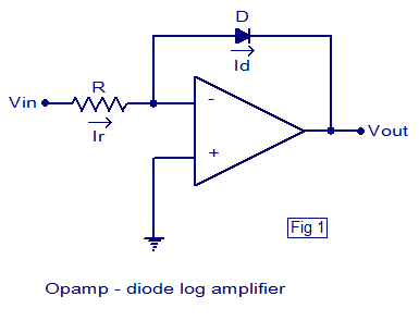
The schematic of a simple Opamp-diode log amplifier is shown above. This is nothing but an opamp wired in closed loop inverting configuration with a diode in the feedback path. The voltage across the diode will be always proportional to the log of the current through it and when a diode is placed in the feedback path of an opamp in inverting mode, the output voltage will be proportional to the negative log of the input current. Since the input current is proportional to the input voltage, we can say that the output voltage will be proportional to the negative log of the input voltage.
According to the PN junction diode equation, the relationship between current and voltage for a diode is
Id = Is (e(Vd/Vt)-1)…………(1)
Where Id is the diode current, Is is the saturation current, Vd is the voltage across the diode and Vt is the thermal voltage.
Since Vd the voltage across the diode is positive here and Vt the thermal voltage is a small quantity, the equation (1) can be approximated as
Id = Is e(Vd/Vt)…………………(2)
Since an ideal opamp has infinite input resistance, the input current Ir has only one path, that is through the diode. That means the input current is equal to the diode current Id.
=> Ir = Id ………………….(3)
Since the inverting input pin of the opamp is virtually grounded, we can say that
Ir = Vin/R
Since Ir = Id (from equation (3) )
Vin/R = Id …………………..(4)
Comparing equation (4) and (2) we have
Vin/R = Is e(Vd/Vt)
i.e. Vin = Is R e(Vd/Vt)……………(5)
Considering that the negative of the voltage across diode is the output voltage Vout (see the circuit diagram (fig1)), we can rearrange the equation (5) to get
Vout = -Vt In(Vin/IsR)
Opamp transistor log amplifier.
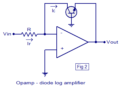
In this configuration a transistor is placed in the feedback path of an opamp wired in inverting mode. Collector of the transistor is connected to the inverting input of the opamp, emitter to output and base is grounded. The necessary condition for a log amp to work is that the input voltage must be always positive. Circuit diagram of an Opamp-transistor log amplifier is shown below.

From Fig 2 it is clear that base-emitter voltage of the transistor Vbe = -Vout ………(1)
We know that Ic = Iso (e(Vbe/Vt)-1) ………….(2)
Where Ic is the collector current of the transistor, Iso the saturation current, Vbe the base emitter voltage and Vt the thermal voltage.
Equation (1) can be approximated as Ic = Iso e(Vbe/Vt) ………….(3)
Ie, Vbe = Vt In (Ic/Iso) …………….(4)
Since input pin of an ideal opamp has infinite input impedance, the only path for the input current Ir is through the transistor and that means Ir = Ic.
Since the inverting input of the opamp is virtually grounded
Ir = Vin/R
That means Ic = Vin/R ……………(5)
From equations (5) , (4) and (1) it is clear that
Vout = -Vt ln (Vin/IsoR1)………….(6)

22 Comments
Purpose of hysteresis in a comparator?
How current characteristics of pn junction employed in a log amplifier?
In your article, saying that for Opamp-transistor log amplifier, “The necessary condition for a log amp to work is that the input voltage must be always positive.” Is there any mistake? I feel the input voltage should be always negative, not positive. Please help me clarify this. Thank you.
What would happen if the input voltage is negative? On both cases.
Why use it for mearsurement light?
Can you please tell me the limitations of basic log amplifier?
what is aplication?
Aren’t these circuits very temperature dependent?. Do you have an idea of how strong this dependence will be?
How to convet the one value into log value
does equation five change if opamp is ideal.
Does the formula change if I add a resistor just before the ground on the diode drawing. the resistor would be between the ground and the positive side of the op-amp
which diode is use in log amplefier?
Pn junction diode
Well, any diode with normal thermal characteristics suffices. The Thermal Voltage for a standard diode comes to 26mV at room temperature of 30 degC
PN junction diode is used.
Excuse me but how can a NPN transistor work when base is grounded?
Because the transistor is in the common base configuration
Please make me clear about the final equation in diode model..Thank you..
i.e. Vin = Is R e(Vd/Vt)……………(5)
e(Vd/Vt) = Vin/(IsR)
ln[e(Vd/Vt)] = ln[Vin/(IsR)]
Vd/Vt = ln[Vin/(IsR)]
Vd = Vt ln[Vin/(IsR)]
Considering that the negative of the voltage across diode is the output voltage Vout (see the circuit diagram (fig1)), we can rearrange the equation (5) to get
Vout = -Vt ln[Vin/(IsR)]
please, i want more explanation about the transformation from equation 5 to the final form equation in the diode model
thnx in advance