Musical Keyboard Using ATMEGA8
This article aims at developing a Monophonic (Single note) musical keyboard by generating the musical notes frequencies using a microcontroller (ATMEGA8). The project presented in this article is a 12 Key, Monophonic keyboard with the options
-
To shift between the Higher and lower octaves
-
Play the programmed tunes
-
Record and save new tune in real-time
Frequencies of Musical Notes
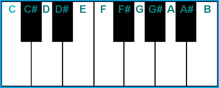
Taking the Piano as a view point, every key of a Piano has a unique frequency. The musical notes are named as:
The frequencies of these notes on a Piano are provided in the following web page – https://en.wikipedia.org/wiki/Piano_key_frequencies .
By knowing the frequency of a particular note from the frequency table, we can play the note using a microcontroller. There are 12 unique key notations as shown in the above image. The frequency of the note depends on the octave of the key pressed. There are 0 to 8 Octaves in a Piano.
Generating a Desired Frequency using a Microcontroller
By using a microcontroller with digital outputs, it is possible to generate square waves with the frequencies of musical notes. The 16-Bit timer-counter of the microcontroller is utilized to generate a square wave with desired frequency. The timer counter is operated in CTC Mode (Clear Timer on Compare Match). Each time when a match occurs between the TCNT1 Value and the Output Compare Registers, the Output Compare 1A Pin is toggled. Every time when a key is pressed, the Output Compare Registers of the Timer1 are loaded with a value corresponding to the frequency of the pressed key. The register defined from the description of registers given in the datasheet:- http://www.atmel.com/Images/Atmel-2486-8-bit-AVR-microcontroller-ATmega8_L_datasheet.pdf
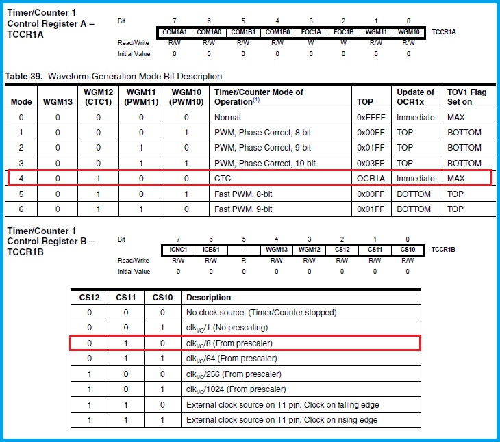
In our application, the register values in hexadecimal format are given below,
- TCCR1A=0X40
- TCCR1B=0X0B
The timer is set to operate at a predefined frequency by selecting the prescaler value. Here, the internal 8 MHz RC oscillator is selected to reduce the external components as well as to have more number of I/O Pins. Now, the Fcpu=8 MHz and by selecting a prescaling value of 8 for the Timer the counting frequency becomes 1 MHz i.e.., it counts 10,00,000 in one second. Let a frequency of 100 Hz is required at the OC1A Pin. The frequency of 100 Hz corresponds to a timer count value of 10,000.
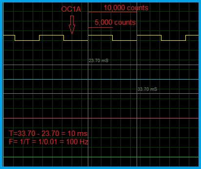
As the waveform should be symmetric, the OC1A Pin stays at the High state for the first half of the time period and at Low state for the second half of the time period. As the frequency of 100 Hz corresponds to a timer count value of 10,000, the Compare Match Register is set to 5000. After the timer counter starts counting from zero, the OC1A Pin toggles (for example, OC1A goes Low) when the count value reaches 5000. The Counter value is reset to Zero by the CPU itself with the timer in running state. Again when the count value reaches 5000 the OC1A Pin toggles again (OC1A goes The High this time). Thus a cycle is completed. This continues until Stop timer command is received.
As per the circuit operation, when a key is pressed the OCR1A (Output Compare Register) is loaded with a value corresponding to the pressed key frequency and the timer is started. When the key is released, the processor waits until the OC1A Pin goes low and then the timer is stopped. Otherwise, if the timer is stopped with the OCR1A Pin in the High state, the speaker draws current even in the silent state because the coil in the speaker acts as a load. Thus a note is played.
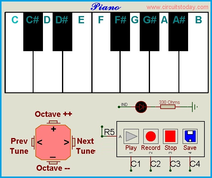
Circuit Diagram
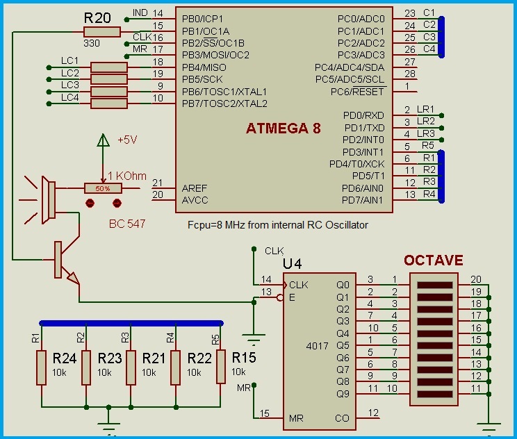
The circuit consists of a microcontroller (ATMEGA8), 20 Keys (Push to ON Switches) arranged in the Matrix keypad (5X4) format, 12 LEDs to show the pressed key, few Pull-Up and Current limiting resistors, a general purpose switching transistor (BC 547) to drive the speaker (Headphones), a 3.5 mm stereo socket to connect the headphones with the microcontroller.
Generating the Frequency after the Key Press
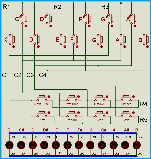
The key is identified in a way that is similar to Interfacing a matrix keypad. For a detailed explanation on interfacing a Matrix Keypad, please go through our article on ‘Interfacing a Matrix Keypad’,
https://www.circuitstoday.com/matrix-keypad-interfacing-proteus
The key 1 to 12 are defined for musical notes and remaining are functional keys. So, when a key press is detected, if the pressed key is between 1 through 12 then, the Timer1 is started with respective frequency by considering the Octave value. To have an addressable access to all the notes, the frequencies corresponding to each octave are framed into a two-dimensional array. The first dimension holds the octave, while the second dimension holds the frequency value of the Nth note. As there are 9 octaves and each octave has 12 unique notes, the size of the array is frequencies [9][12]. To call the note with its key number, let’s frame the notes from 1 to 12 locations of the array thereby leading to the array size of frequencies [9][13]. The frequency table is provided below in a two-dimensional array. The frequency array contains the notes in terms of C,C_ and so on.., which are equal to keys 1 to 12. These are defined in the global declaration part of the program. These alphabet notations can be replaced with actual numbers.
Program/Code
Musical Keyboard Using ATmega8 – Download Frequency Table Code
The program file is provided below which is compiled by using the ‘winavr’ open source software.
Musical Keyboard Using ATmega8 – Download C Program for the Project
Frequency Table
Now, by using this array we can play any note. For example, if we want to play the note C5 (‘C’ note of 5th Octave) then, we have to call ‘frequencies [5][1]’. Thus, after detecting the pressed key, the respective note is played. Remember that the default Octave is programmed to Octave 4, which can be varied in real-time. The piano contains notes up to ‘A8’. Notes after this location are repeated with A8 in the given array.
Showing the Pressed Key/Note
The circuit contains an indicator for each of the 12 notes. This will not only show the pressed key but also indicates the note that is being played while playing a tune. As there are 12 notes we may require 12 I/O Pins of the microcontroller in general. But here we have used the matrix technique. This reduces the number of I/O Pins from 12 to 7 by using a 4X3 Matrix configuration. The LEDs are arranged in such a way that, there are four columns and three rows. The columns are anodes of the LEDs and the Rows are Cathodes of the LEDs. In order to enable an LED, its column Pin should be given Logic 1 and the row Pin should be given Logic 0.
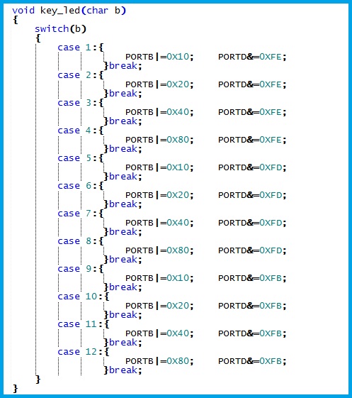
Each time when a key is pressed the respective LED is enabled immediately after key identification. After the key is released, the LED is disabled. While playing a tune, the LEDs are enabled by calling a user-defined function which is declared as ‘key_led()’. The audio output in the below video shows the difference between one octave to the next octave and shows the pressed key through its LED.
Varying and Showing the Octave
After detecting a key press, if the key is not within 1 to 12 then, the functional keys are verified through a ‘switch statement’. The cases 15th and 16th are the keys 15 and 16 which are dedicated to raise and lower the octave value. A decade counter is used to show the currently selected octave. If a microcontroller with a higher number of I/O Pins is chosen then, this decade counter can be eliminated and indicated directly from the I/O Pins of the controller.
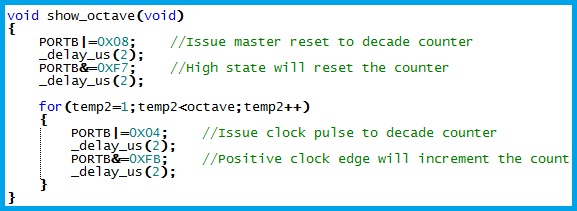
If Key 15 is pressed then, the octave value is incremented up to 8 otherwise if the key 16 is pressed then the octave value is decremented up to 0. After every incrementation/decrementation, a Master Reset signal is given to the decade counter and a series of counting pulses equal to the updated octave value is given to the decade counter thus, showing the current value of the octave on a Bar-Display. Then after, if any one of the 12 notes is pressed then, the frequency corresponding to this note and the updated octave is played.
Playing a Programmed Tune
Every tune contains some finite number of notes played in a cyclic manner. The note cycle has four bytes of information.
-
Octave of the note
-
The note itself
-
Duration of note
-
Time Gap that should be given before playing the next note
By placing such note cycles one after the other a tune can be formed. For a single tune, a one-dimensional array can be used to store a tune. The 0th location of the array contains the total number of locations used in the array to know the end point of the tune.
The first location of a note cycle contains the octave of the note and the second location contains the actual note number. Now, the third location contains a value proportional to the duration i.e.., duration=1 indicates the timer counter has to count from 0 to 255 with a clock frequency of Fcpu/256. Similarly, the fourth location contains a proportional value of time gap between two notes. The minimum value of these durations is 1.
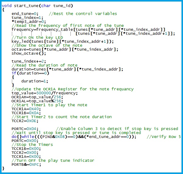
When the command is received to play a tune, the first note is read from 1st and 2nd (octave and the note) locations of the respective tune array and duration of the note is loaded in the ‘duration’ variable from the third location of the array. Now, the Timer2 is started and the processor enables the column containing the stop button and stays in a ‘do while’ loop until the tune is completed. An interrupt is generated every time after counting 255 and a temporary variable ‘temp3’ is incremented in the interrupt sub-routine and verifies whether this temp3 is equal to duration. If temp3 is equal to duration then the Timer2 is stopped and also Timer1 is stopped to stop playing the note. Now, the temp3 variable is reset to 0 and the fourth location of the ‘tune’ array is read to get the duration between the first note and the second note. Again the Timer2 is started verifies for temp3 equal to duration. If found equal then the Timer2 is stopped temp3 is reset and the cycle is repeated to play the next note. This repetition continues until the tune_index is less than the tune’s array size (the value in the zero location of the tune). The interrupt sub-routine to play the tune continuously after starting is shown below.
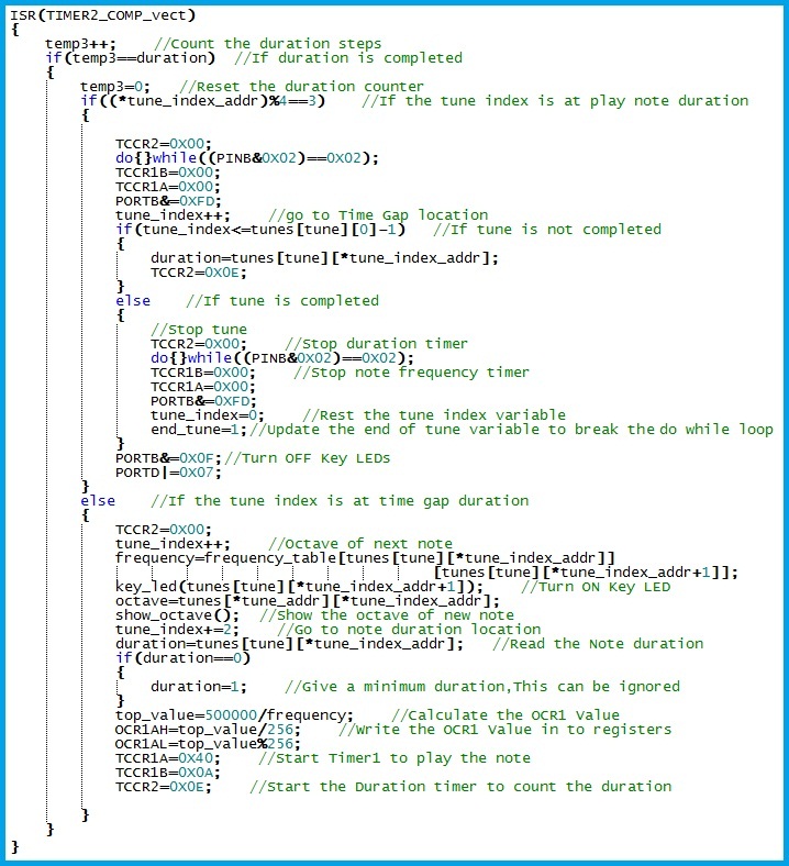
When the tune_index reaches the end location of the tune, the variable ‘end_tune’ is updated to a value 1. This ‘end_tune’ variable is verified to come out of the ‘do while’ loop. The ‘do while’ loop also monitors the stop button while the tune is played. If the stop button is pressed while a tune is being played, the ‘do while condition’ becomes false and the tune is stopped playing by stopping the timers.
In the present program, the ‘Happy birthday’ tune is programmed to the tune[1] array. We can add desired tunes in tune[2], tune[3] and so on.., by defining them in declaration part. The number of programmed tunes is considered while incrementing and decrementing the ‘tune’ variable in the instructions related to the ‘Next’ and ‘Previous’ tune buttons.
Recording a Tune
To record a tune, the procedure followed to play a tune is followed in reverse direction i.e.., the four bytes of note cycle are read from the inputs given by the key switches to the microcontroller. When a key is pressed the frequency is generated as usual. To record the information a timer is started and then, the octave of the note, the key number is written to the ‘tune’ array. Here, we are writing the recording tune in ‘tune[0][tune_index]’. After the key is released, the timer/counter is stopped and the count value is stored in the array. Then again the timer is started to get the time gap between first key press and the second key press (the silent duration). When the second key is pressed, the timer is stopped and the count value is stored in the array. The array index is incremented whenever required. Thus, the information for one note cycle is read and written in the RAM of the microcontroller.
After playing the desired ‘tune’, the user will press the stop button. The user can preview (prelisten) the played tune and if satisfied with the tune can be saved by pressing the save button.
The TIMER0 is used to count the durations. The Timer0 is operated at Fcpu/256 (Prescaler=256) and the Overflow Interrupt is enabled. Each time when the overflow occurs, the variable timer0 is incremented by 1 in the Timer0 Overflow Interrupt sub-routine. The register values for the duration counters to play a tune and record a tune in hexadecimal format are given below,
-
TCCR2=0X0E for Timer2
-
OCR2=0XFF
-
TCCR0=0X04 for Timer0
Saving a Tune
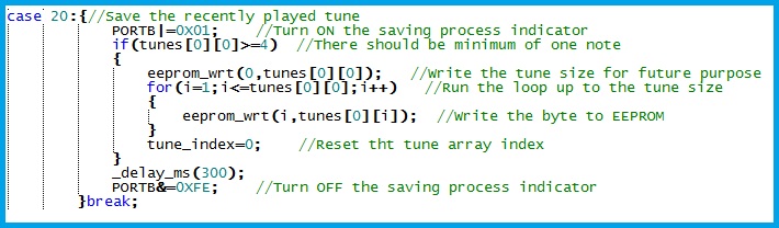
The save option will write the tune in the EEPROM. The tune index is written in the 0th location of the tune[0] array. A for loop runs for a number of times equal to this tune_index and writes the tune array into the EEPROM. While POWER ON or restart this tune is copied into the tune[0] array. This tune remains in the EEPROM until another tune is recorded. The program can be easily modified to store multiple tunes by using a microcontroller with sufficient RAM and EEPROM sizes.
The speaker used here is the headphones, but this can be connected to an amplifier. One of the possible amplifier circuits is present in the article below,
https://www.circuitstoday.com/stereo-headphone-amplifier
The program file is provided below which is compiled by using the ‘winavr’ open source software.
Comments are closed.