Programmable LED Message Board Circuit
In this article, the idea and implementation of remotely editing the text or message of the LED Matrix Display (Custom LED Signs) are presented. This article is the continuation to the article – LED Scrolling Display Board Circuit Using AVR Microcontroller which explains
- The Framing of Alpha-numeric characters and special characters.
- Showing a standstill message
- Scrolling the message
- Varying the speed of scrolling
The message or text can be edited to bring custom LED signs by connecting the Display to a computer using a Serial cable (RS-232). The RS-232 Voltage level is converted to TTL Level using a level shifting IC (MAX 232). The serial data sent by the computer is then processed by the microcontroller of the Display circuit. The new message is stored in the EEPROM of the microcontroller. At every start-up or Power ON, this data is read from the EEPROM of the microcontroller and thus the message is displayed.
The idea is not limited to computer-based editing. It can be applied to any type of data transmission, which uses UART mode of serial data transmission, it may be wired or wireless. Nowadays, the Bluetooth feature of the smartphones is commonly used for remote control applications. The same can be used to edit the message of the Display as well. Below is the demo which shows editing the message using Bluetooth feature.
Programmable LED Message Board – Video Demo
Now, let’s see how to edit the data of the LED Matrix display using the Bluetooth feature. For this purpose, from the data sending end, a smartphone installed with a Bluetooth chat Application is required. In the data receiving end i.e., in the LED Display, a Bluetooth module is required (HC-05 is used in this article). The UART Peripheral of the microcontroller is used to interface the Bluetooth module.
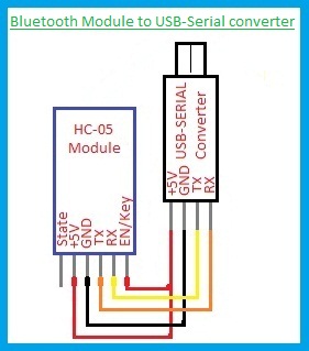
The Bluetooth module should be configured as a slave that accepts connection with any device. The module should be connected to a serial terminal to interact with the module. For this purpose, a USB-TTL Serial converter is used. Connect the module to USB-TTL serial converter as shown below.
This configuration is required if we want to change the parameters of the module. Otherwise, this part can be skipped off. The program flow contains verification of password within the entered message. So, the system is secured even if an unknown device connects to the module.
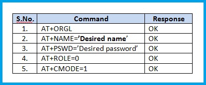
By connecting the converter to the USB Port of a computer, the module will be powered ON. Now, enter into AT command mode by pressing the push button on the module. This procedure is different for different modules. So, enter into AT Command mode and set the name and password module of the module as desired by sending respective commands. Some of the commands are shown below. This password is just to connect to the module which is generally ‘1234’. We will use another password to edit the text.
Receiving the Data by the Microcontroller
The ‘UART RX’ Interrupt of the microcontroller is enabled and each byte received is stored in the ‘text’ array. If the received data matches with the predefined format, then the password entered is verified and if the password matches, the text is edited. Below is the format of text that should be sent by the smartphone.
*PASSWORD*TEXT#
As seen in the above format, the user has to type the password along with the text. So, even if an unknown device connects to the module, the text cannot be edited without knowing this password. When the character # is received by the microcontroller, it starts editing the text. A timer interrupt is used to initiate the editing process. The new text will be stored in the EEPROM.
Changing the Password
The password can be changed in real-time by sending the new password in a pre-defined format. The password must be of 4-characters and it can be alpha-numeric. Below is the format,
!OLD PASSWORD!NEW PASSWORD#
From the above formats for editing the text or the password, it can be observed that ‘#’ is used as the end of text indicator. So, ‘#’ should not be used in the text. This can be modified with any other character if desired. This is chosen because all of the Bluetooth chat Apps does not send CR or LF or any other end of transmission indicators. If an App is designed especially for this purpose or if a Bluetooth chat App with an end of transmission indicator is available, then ‘#’ can also be used in the text.
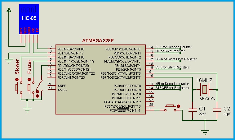
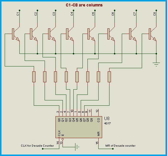
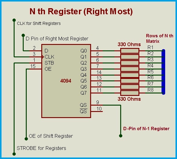
Below is the circuit diagram in which the microcontroller ATMEGA 328P is used. The remaining circuit is same as that of the previous article, which is provided below for ready reference.
Bluetooth Based Programmable LED Message Board Circuit – Program File
Download Program File
Bluetooth App used - Click Here
The program is compiled using mikroC pro for AVR. The default password and text to be displayed should be loaded into the EEPROM while burning the program code into the microcontroller. Remember to add the end of text indicator which is decimal value 13 (=0D in Hexa decimal). If password is forgotten, the EEPROM address locations from 1 to 4 should be written with a new password, as entered during burning the program code or a factory reset option can be provided if desired.
The Programmable LED Display Board can also be edited through SMS Feature by using a GSM Module. The program needs to be modified a little to read the message received by the GSM Module. Rest of the code and technique remains the same. Interested readers can go through the article on Interfacing GSM Module using Proteus for a detailed Explanation.
Comments are closed.