Interfacing GSM Module Using Proteus
The Proteus simulation software can be used to interface real-time modules like the GSM Module. By using this simulation feature the designer can develop the systems within the software and test all the features of the system that is under design without using any hardware components. The system can be standardized by comparing the performance of various components, like, for example a suitable microcontroller. This article explains how to connect a GSM Module to the Proteus software and understand various commands related to the GSM module and perform some operations like sending an SMS, reading an SMS, making phone calls and so on.
Connecting the Module to Proteus Environment
The GSM modules have the option to connect to the serial port of a computer through DB-9 Connector or it can be interfaced to a microcontroller using the TTL-UART feature. The Proteus software has the option to connect with the com ports of the computer. If the serial port is not available on your computer, then a USB-Serial converter can be used. The circuit diagram is shown below.
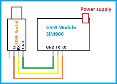
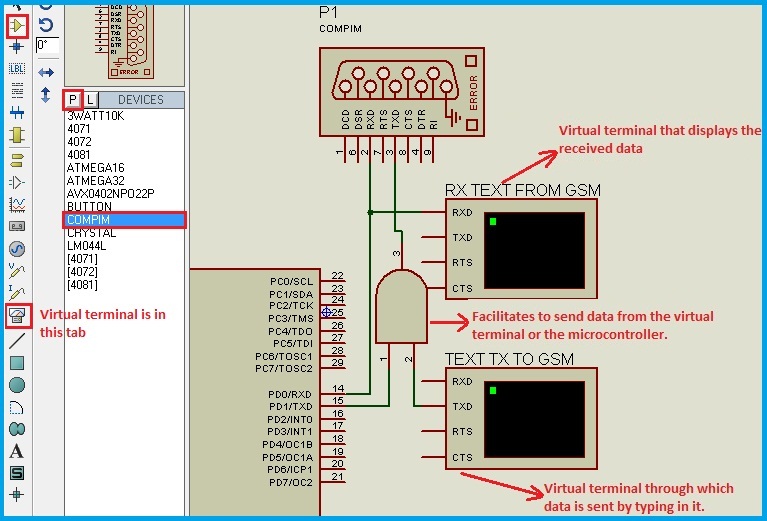
The component ‘COMPIM’ Comport Physical Interface Model is used to connect the proteus circuit with the serial port of the computer. The virtual terminal in the Instruments tab is used to view the data which is transmitted and received through the selected serial port.
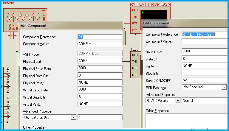
Next, we have to configure the COMPORT in the Proteus software. By default, the modules operate at 9600 Baud rate. If there is any malfunctioning with respect to the data received, then next probable baud rate would be 38400. The data is of 8-Bit mode with one stop bit and no parity. All these parameters should be set in the Comport and the Virtual terminal in their edit properties menu.
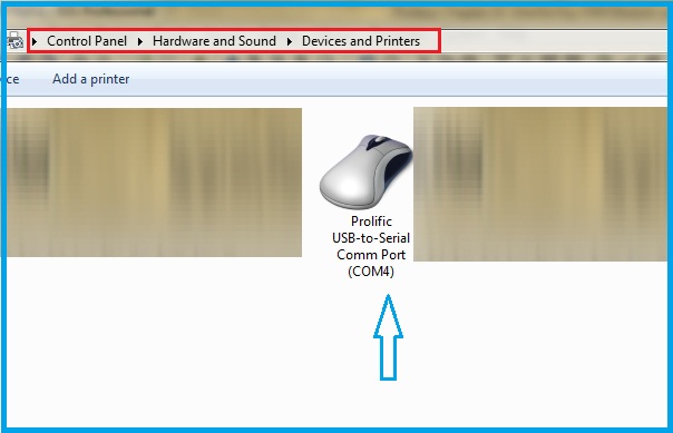
The details regarding the port number to which the Serial converter is connected are obtained from the control panel under the Devices and Printers tab.
We shall start interfacing the module. To check whether the connection is established or not, run the simulation and then Power ON the module. The module sends some data related to the ready state of the module. Below is the simulation video showing the responses after Power ON.
After the response ‘call ready’ is received, the module is ready to use. All the command characters are viewed as ASCII characters. In the C-compilers temp=‘0’; instruction will store the ASCII value of zero (=48) in the variable temp. Every command sent to the module has to end with <CR><LF> i.e., CR=Carriage return and LF=Line Feed characters whose ASCII values are 13 and 10 respectively.
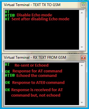
In order to check the connection, we can send the ‘Attention command’ ‘AT’. If the connection is established, ‘OK’ is received. The module will resend the characters received by it. This is called the Echo mode and this can be avoided by using the command ‘ATE0’. After successful execution, ‘OK’ is received.
Make a Phone Call
The command to make a phone call is ‘ATD’. This is called as originating a phone call from the module. The command is used in the following format,
ATDPHONE NUMBER;
Ex: ATD1234567890;
Let’s try this command to originate a phone call. Below is the output.

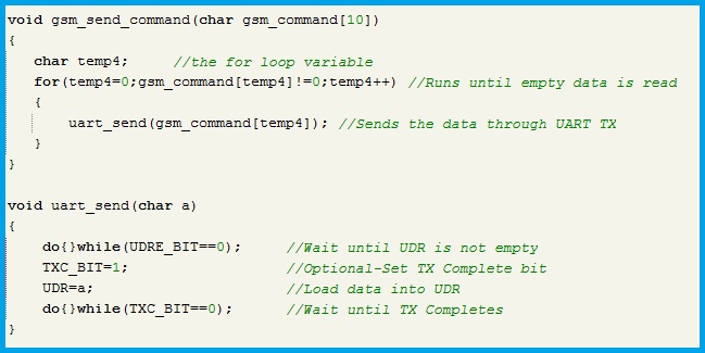
This command is issued from the virtual terminal available in the software. But, in real-time we have to issue this command from our microcontroller. Let’s frame and issue the command through the microcontroller. By using arrays in the c-program, we can easily transmit the commands. For this purpose, we have to define a function to send the ‘gsm commands’ and one more function to send data from the UART. Below are the function definitions.
The ‘gsm send command’ function is used for sending the keywords of the command as a text written with in quotation marks, like for example,
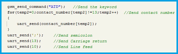
gsm_send_command(“ATD”); which is the dialing command used previously. After sending this keyword, we have to send the destination number i.e., the contact number to whom we want to call. Any data should be stored in the array format so that, the data can be handled by all the functions in the program. For making phone calls, we have to declare an array to store the contact number. The size of the array can be around 20 bytes (the module allows up to 45 digits) and it should be of ‘char’ type because the data is in ASCII format. The contact number is declared as char contact_number[20]; This can be assigned with a default number as, char contact_number[20]={‘1’,’2’,’3’,’4’,’5’,’6’,13}; Writing a character inside Apostrophe loads the ASCII value of the character in the respective address location. The last character should be decimal value 13 for identification of the end of the array data, so that while sending the data we can stop it after finding ‘13’. This can be modified according to the programmer. The contact number is sent using a for loop,
for(temp2=0;contact_number[temp2]!=13;temp2++)
{
uart_send(contact_number[temp2]);
}
Next, we have to send the semicolon ‘;’ whose ASCII value is ‘59’. Every command line has to end with CR and LF i.e., the Carriage return and Line feed characters, whose decimal values are 13 and 10 respectively. The complete code is shown below.
Thus, the dialing command line is completely transmitted as shown in the below simulation output:-
Reading an Incoming Phone Call Details
The caller information is sent by the module whenever an incoming call is detected. By reading the received data, we can fetch the Caller information like the Contact name (if already saved in the memory) and the Contact number. The data sent by the module for an incoming call is shown in the below image.
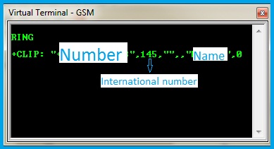
From the above image, the format of the data can be understood as:-
<CR><LF>RING<CR><LF>
<CR><LF>+CLIP: “NUMBER”,type of number,””,,”NAME”,0<CR><LF>
The CR and LF are not visible characters as they control the cursor position but, they are countable ASCII characters. To extract number and name from the received string, let’s go with the following approach. The received data is stored in an array whose starting address is zero and this zero location contains ‘<CR>’. By verification process, let’s find the first quotation character using ‘do while’ loop.
temp=0; //Initialize a temporary variable
do
{
temp++; //Increment temp value by one
}while(received_data[temp]!=34); //Check whether the character is “ or not
ASCII Value of “ is 34. When the quotation is found, the Instruction pointer comes out of the loop as the condition is not satisfied. Now, the temp variable contains the address of the quotation character and the next address location has the first letter of the number and this continues until next Quotation is encountered. So, let’s store the number into an array using the ‘for loop’.
temp++;
for(index=0; received_data[temp]!=34;index++,temp++)
{
number[index]=received_data[temp]; //Store number
}
number[index]=13; //Terminating character for identification
Now, received_data[temp] location contains quotation mark and hence the loop is completed. To fetch name from the data, the above process is repeated. The complete code to obtain number and name is shown below.
CLIP in the data received stands for Calling Line Identification Presentation. To know whether the code is working as expected or not, let’s use a display to show the collected data. The name and number are displayed soon after an incoming call is detected.
When there is an incoming call, we may have to answer the call or reject the call. The respective commands for these operations are,
ATA will answer the call
ATH will reject the call
By sending the commands, the respective operation is performed. If we connect ear phones or a head set to the GSM Module, we can use it as a normal phone.
By now, we have discussed how to read the received data for a particular like when ‘RING’ is received. We have seen it in the Virtual terminal and performed the action. But, in real-time, the microcontroller has to read the data and identify that ‘RING’ is received. The GSM Module has hundreds of keywords out of which only a few are used for specific applications other than a full-fledged mobile phone. Now, let’s discuss how to identify the keywords and execute the desired operation.
Reading the keywords from data received
The UART feature has an RXC Interrupt which will generate an interrupt when a byte is received. By enabling this interrupt, every byte sent by the module is stored in a variable of array type and the array index is incremented. The GSM Module does not send any command to indicate finish of transmission. The CR and LF are used to detect command line termination only and these are sent in between a command line also. So, to identify that the transmission is completed by the module, a timer is used. After receiving every byte the timer is stopped, the byte is stored in the variable and the timer is initialized again. If the counter reaches a pre-set value before reading the next byte, then it is understood that the transmission is completed and the data is processed. After processing the data, the array index should be set to zero. The code for the procedure discussed is shown below.
The timer/counter preset value is defined such that a time interval of around 100 to 200 mSec is achieved. For ATMEGA 32, which is used in this article has the below values for 16Mhz CPU Clock, and the timer is run at Fcpu/1024.
OCR1AH=0X0E;
OCR1AL=0X00;
These are the output compare match registers.
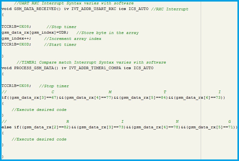
The first byte of the command line received will be CR (Decimal value=13) and the second byte will be LF (Decimal value=13). So, we can start verifying from third or fourth byte i.e., from the second or third address location of the array depending on the keyword under consideration. This is applicable to all the keywords as we know them while programming. For phone call related operations, there is an option to receive keywords in the numeric format instead of words. Some of the responses that are mapped to numbers are shown below. The numeric values are just like substitutes for the respective words, but remaining format like CR and LF are same.
| ATV1 | ATV0 | Description |
|---|---|---|
| OK | 0 | Command Executed |
| CONNECT | 1 | Connection is established |
| RING | 2 | Incoming call is detected |
| NO CARRIER | 3 | Connection is terminated or cannot connect |
| ERROR | 4 | Command not recognized |
| NO DIAL TONE | 6 | Dial-tone is not detected |
| BUSY | 7 | Engage signal is detected |
The numeric mode is selected by sending the command ‘ATV0’.
‘ATV1’ is sent to receive in word format as mentioned in the header of the above table.
SMS Related commands
The SMS based systems are more usual and can be used to perform various tasks remotely. The text type SMS are discussed here. In order to perform SMS based operations, it is mandatory to set the message related formats with the desired parameters. Basic parameters which are sufficient for general operations are discussed below.
AT+CMGF=1
This command sets the Message Format to text mode.
AT+CNMI=2,1,0,0,0
On execution of this command, the module will send indication after a new message is received. CNMI Stands for New SMS Message Indications
AT+CMGS – Send an SMS
This command is used to send an SMS from the module. The format of this command is,
AT+CMGS=”Destination number”<CR>
Wait until ‘>’ character is received and enter the message.
Press ‘ctrl-z’.
The message will be sent and acknowledge is received with the storage index.
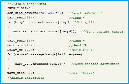
The above show procedure should be done by the microcontroller. Let’s develop the program code to send an SMS. As discussed in the Phone call example, the destination number is stored in an array and the ‘gsm send command’ function is used. After entering the number we have to wait for ‘>’ character is received. So, we will include a delay function. But, how to press ‘ctrl+z’? The ASCII Value for that command is ‘26’. So, after sending the text of the message, send the value ‘26’ as an ASCII Character. Below is the code for the procedure discussed.
AT+CMGR – Read an SMS
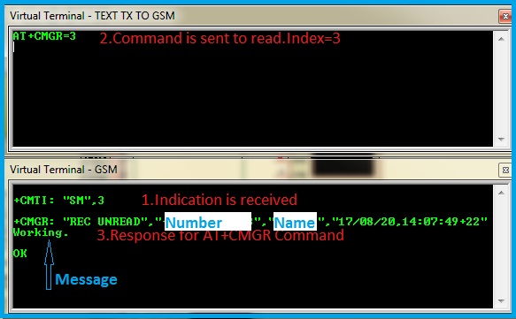
The Module sends the new message received indications. Below is the data sent by the module after a new message is received.
+CMTI: “SM”,Message index
SM-sim memory
As the module does not have external memory, the SIM memory is used to store the received, the sent and the unsent messages. The message index is the address location of the message, which is used to read the message. The format of this command is,
AT+CMGR=<Message index>
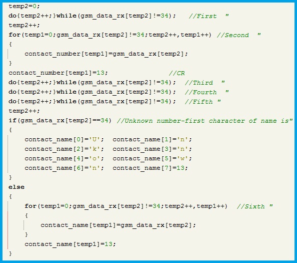
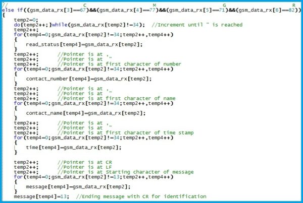
The microcontroller has to analyze the data received in response to this command and fetch the message details like the sender’s number, contact name, the time stamp and finally the message. Below image shows the format:-
Now, let’s read the response and extract the message from the received data.
For every message, there are four message details and one message string. From the above image, the read/Un read status starts after the first quotation mark. So, to read this status we can use ‘do while loop’ as used previously in making a phone call. Similarly, remaining details like number, name and timestamp are stored. After the timestamp quotation mark, the message is received in the new line. This indicates that <CR> and <LF> are sent before the message. So, increment temp variable two times and store the data in the message variable until <CR> is read.
AT+CMGD – Delete an SMS
While developing autonomous systems which do not involve human interface or monitoring, deletion of messages is very essential. If the SIM memory is full, the module stops sending new message indications. Hence, it is better to delete the processed message. If the message has to be used in the future, then it has to be stored in external memory. To delete a message, its index should be known. The command line is,
AT+CMGD=<Index>,<Deletion type>
The index is available in the RAM while reading the message. Deletion type involves 5 kinds.
| Type | Description |
|---|---|
| 0 | Delete the message with the specified index. |
| 1 | Delete all read messages. |
| 2 | Delete all read and sent messages. |
| 3 | Delete all read, sent and unsent messages. |
| 4 | Delete all read, sent, unsent and unread messages. |
The message index is not a continuous variable, i.e., if a new message is arrives at index 10, the next arrived message occupies the empty address location which may or may not be 11. This is because of the deleting command. Suppose there are 15 messages from 1 to 15 indices, if we delete a message with index 5, then the next incoming message will occupy this location i.e., the index 5 and only then the 16th index will be occupied by the next message.
AT+CMGW – Write message into memory
This command is used to write a message into memory and send it whenever required, instead of writing the message every time. This option is useful in developing the systems which have to send some fixed messages like the templates. The stored messages can be sent using their indices. For this purpose, the message is stored first and the received index is stored in the non-volatile memory of the system. When the message needs to be sent, this index is used.
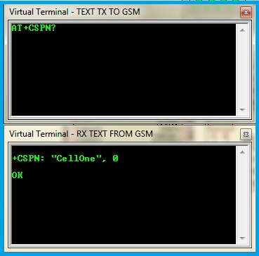
AT+CSPN – Inquire the name of Service provider
The name of the service provider can be known by using this command. The command format is,
AT+CSPN?
The response would be,
+CSPN: Name,Display mode
Below is the command execution output:-
AT+CCLK – To get clock time
This command is used to get the clock time. But, this clock has to be set before reading. The command to set the clock time is,
AT+CCLK=”yy/mm/dd,hh:mm:ss+zz”
+zz is the zone difference indicator. This value ranges from -47 to +48. This value should be set according to your time zone. For example, if the time zone is GMT+4:30 Hours the zz value is ‘+18’ i.e., add 2 for every half an hour. 4:30 Hours contain 9 half hours and so the value is 18.
Once this clock is set, the time can be inquired. The response would be
+CCLK=”yy/mm/dd,hh:mm:ss+zz”
AT+GSMBUSY – Sets the module in busy mode
We have the option to set the module in the busy mode to reject the incoming calls. This option is used to provide call waiting feature.
AT+GSMBUSY=0 will allow the calls even if there is an incoming call in answering state.
AT+GSMBUSY=1 will disable the incoming calls irrespective of the state of the module.
While designing SMS based systems, we can enable this mode so that, even if anyone calls to this system, they get a busy tone.
Comments are closed.