In this arduino project, we are detailing a line follower robot using arduino, a couple of LDR sensor pair, and two motors. A line follower robot is a very basic project to start with, when you are learning a new micro controller like 8051 or AVR or PIC.
Line Follower Robot using Arduino – DIY Electronic Project
A line follower robot using 8051 microcontroller is already published in CircuitsToday and this time the same project is rebuilt using arduino. This line follower robot is basically designed to follow a black line on a white surface. Any way the same project can be used to follow the opposite configuration with appropriate changes in the software.
The entire hardware of this simple line follower robot using arduino can be divided into three parts; The sensor, Arduino board and the motor driver circuit. Lets have a look at the sensor first.
1. Sensor
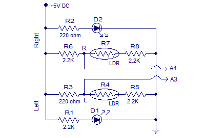
The sensor consists of two LED/LDR pairs with appropriate current limiting resistors. The resistance of an LDR is inversely proportional to the intensity of the light falling on it. The circuit diagram of the sensor is shown in the figure below.
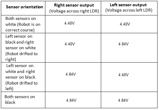
Resistors R1 and R2 limits the current through the LEDs. Resistors R6, R8, R3,and R5 forms individual voltage divider networks in conjunction with the corresponding LDRs. When the sensor is correctly aligned, both LED/LDR pairs will over the white surface. In this condition sufficient amount of light gets reflected back to the LDRs and so their resistance will be low. So the voltage dropped across the LDR will be low. When the robot is drifted to one side , the sensor in the opposite side falls over the black line and the intensity of light reflected back to the corresponding LDR will be low. As a result the resistance of the LDR shoots up and the voltage dropped across it will be high. The voltages dropped across the right and left LDRs (nodes marked R and L in the above circuit) are given as input to the analog input pins A4 and A3 of the Arduino board. Right and left sensor outputs observed while testing the above circuit is shown in the table below.2. Arduino uno board
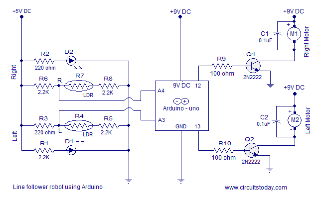
The arduino board has to be programmed to keep the robot in correct path. This is done by reading the left and right sensor outputs and switching the left and right motors appropriately. Output of the right sensor is connected to the analog input A4 of the arduino and output of the left sensor is connected to the analog input A3 of the arduino. The voltage range that can be applied to a particular analog input of the arduino is 0 to 5V. This range can be converted into a digital value between 0 and 1023 using analogRead () command. For example if 3V is applied to A3, the following code will return 3/(5/1023) which is equal to 613 in the variable leftValue.
int leftInput = A3;
int leftValue=0;
void loop ()
{
leftValue = analogRead (leftInput);
{
From the above table you can see that the voltage across a particular LDR will be 4.4V when it on white and 4.84V when it is on black. The digital equivalent of 4.4V will be 900 and that of 4.84V will be 990 as per the above scheme. The median of these two values is 945 and it is set as the reference point for the program to check the orientation of the sensor module.
The program identifies the position of the sensor module by comparing the sensor readings with the reference point that is 945. If the reading of a particular sensor is greater than 945 the program can assume that the particular sensor is above black. If the reading of a particular sensor is less than 945 then it is assumed that the particular sensor is above white. If both sensor readings are less than 945 then it means both sensors are on white. If both sensor readings are above 945 it is assumed that both sensors are above black (the same thing happens if we lift the robot off the track). Based on the above four conditions, the program appropriately switches the left and right motors to keep the robot following the black line.
3. Motor driver
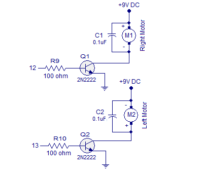
The motor driver circuit is based on two NPN transistors Q1 and Q2. Each transistor is wired as a switch with a resistor at its base for limiting the base current. The motors are connected to the emitter terminal of the corresponding transistors. A 0.1uF capacitor is connected across each motor for by-passing the voltage spikes. Back emf and arcing of brushes are the main reason behind the voltage spikes. If these voltage spikes are not by-passed it may affect the Arduino side. Circuit diagram of the motor driver is shown in the figure below.
Circuit diagram – Line Follower Robot using Arduino
Full circuit diagram of the line follower robot is shown in the figure below.
Program
int leftInput=A3;
int rightInput=A4;
int leftMotor=13;
int rightMotor=12;
int leftValue = 0;
int rightValue = 0;
void setup()
{
  pinMode (leftMotor, OUTPUT);
  pinMode (rightMotor, OUTPUT);
}
void loop()
{
  leftValue = analogRead (leftInput);
  rightValue= analogRead (rightInput);

 if
   ( leftValue < 945 && rightValue < 945)
   {
     digitalWrite (leftMotor, HIGH);
     digitalWrite (rightMotor, HIGH);
   }
   else
   {

     if
     ( leftValue > 945 && rightValue < 945)
    {
      digitalWrite (leftMotor, LOW);
      digitalWrite (rightMotor, HIGH);
    }
 else {
   if (leftValue < 945 && rightValue > 945)
   {
   digitalWrite (rightMotor, LOW);
   digitalWrite (leftMotor, HIGH);
   }
   else
   {
     if (leftValue > 945 && rightValue > 945)
     {digitalWrite (rightMotor, LOW);
       digitalWrite (leftMotor, LOW);
     }}
      }
    }}
Setting up the circuit
- First of all, remember that each LED and LDR has its own characteristics.
- Carefully measure the voltage across each LDRs in both scenarios (on a white surface and black).
- A lot of parameters like individual LDR/LED characteristics, ambient light, the clearance between sensor and surface etc may affect the result.
- Get into your own reference point for the program. In my case, it was 945 but you may get a different value.
- Use a separate power supply unit for powering the motors. Anything above 100mA will be hard for the USB port.
- The motors used here are 9V/30RPM DC bow motors. If such a configuration is not available, choose the closest one.
- While soldering up the sensor module, the gap between the two LED/LDR pairs must be selected according to the width of the black line. In my case it was 2cm.
- Clearance of the sensor from the ground was around 1cm in my case.
- The sensor LEDs used were 4mm bright green LEDs.
- The sensor LDRs used were general purpose LDRs.
If you are interested in making this using 8051 microcontroller check this post of ours – Line follower robot using 8051 microcontroller


33 Comments
How the resistors on the rung of LDRs are calculated??
Sir, We have 2 pins each that come out from the motor controller. Is there any way to configure it so we can have a pin each from each motor? or is there any other coding strategy that helps to control the motor? Please reply as soon as possible.
In this code, the left motor is configured to pin 13 and the right motor to pin 12.
sir I am making one using the above
instructions.But I am having a problem understanding the structure of the robot so will u plz post a pic of your robot.
hi friends..
I have purchased a Line following Robot from it. I am fully satisfied with the quality of products. Goods shiping out so fast. Great costumer care service! Very good discounts system! I like this online store , I will purchase Again from http://www.Robomart.com
Having a go at the line tracker using an arduino uno. I noticed in the schematic that R1 and R2 are different values, 2.2k and 220 Ohm and R3 and R6 are also different. I assume they have been transposed. what are the intended values. Also what does “bow” refer to in the motors specified.
Hi Steve, R1 & R2 are used for Leds. so it has to be 2.2k. It is used to protect the Leds from getting damaged. You can even different value resistance,like 1K, but it depends on your power supply. It is better to use 2.2k from 9V to 12V supply.
EVERYBODY PLEASE LISTEN.
the way it is shown in this tutorial, that you calculate potential drop across…. blah blah blah…
all rubbish.
Most of the time it will not work.
you need to see actual arduino readings for this.
just code –
int analogPin = 3; // Infrared Sensor (Right lead) connected to analog pin 3
// outside leads to ground and +5V
int val = 0; // variable to store the value read
void setup()
{
Serial.begin(9600); // setup serial
}
void loop()
{
val = analogRead(analogPin); // read the input pin
Serial.println(val); // debug value
}
in arduino and insert a pin from sensor in A3, and then on arduino software, goto tools-serial monitor.
then start serial monitor, while POWERING SENSOR BOARD BY ARDUINO.
For that, insert the positive of sensor board in arduino board power section “5V”, and negetive in “GND”.
then read and note values on screen, while sensor is kept on white, and on black. and then change values in the code in the tutorial, according to you.
THANK YOU..
Sir,
I followed every step that u told in the guide. but i wanted to tell, if we power arduino board from 9V battery, and same battery powers up motors also, then only motor works, else if i use different powerups for motor and arduino, motors don’t move not on black and on white too. but if i powerup both by same battery, both the motors work on all surfaces. PLZ HELP me , where i could be going wrong. PLZ its really very urgent plz.
@Pulkit – You could have missed proper “Grounding”. When you use 2 different power sources, make sure you have the ground common for both sources.
Sir, i wanted to ask whether LDRs length should be more than LEDs?
and moreover i followed ur circuit diagram but when i connect complete circuit, Both motors work even when they are kept on black. Please reply as soon as possible. And please tell me possible mistakes i would have made. Please its REALLY IMPORTANT.
and moreover ,my reference points were different and i had changed the values according to them.
PLZ HELP
can anybody send me the detailed project report pleazzzz….
Can i use +5Volt power that can be provided by Arduino to power up sensor module??
are u asking how will u provide 5V to power up sensor module?
Sir i wanted to know that how to control the speed of motor with coding. And i want to learn full meaning od coding and each steps so can u plzz tell me how doest it works. I had made a simple robot with coding which can move in all directions but not with any sensor. So plzz tell me how to code with sensors
Sir can u tell me how to install the programme in ardiuno bord..??
Sir can u send me a photo of d arduino uno board connection.. And plz tell me how to install the programm on arduino board… !!
@Ahmad,
We have tested this with a working model. May be you should check for any errors in Proteus design created. We have tested the same model using 8051 as well. You can see this here – https://www.circuitstoday.com/line-follower-robot-using-8051-microcontroller
what the 945 value at the program how u got the value
voltage across an LDR will be 4.4V when it above white surface and 4.84V when it is above black stripe. The digital equivalent of 4.4V will be 900 (when converted by the avr328 adc) and that of 4.84V will be 990 as per the above scheme. The average of these two values is 945 and it is taken as the reference point to check the position of the robot.
If the reading of a sensor is greater than 945 is assumed that the sensor is above the black stripe. If the reading of a particular sensor is less than 945 then it is assumed that the sensor is above white surface.
sir, i’m making a line follower robot with arduino UNO R3 ATMEGA 328 . SO IT IS TRUE THAT IT WILL FOLLOW A black line on a white surface but will it move even if there is no such line with help of arduino.. why and if not ….pls. tell me how to do so……….pls……..
sir I wanted to ask that if the rduino uno board is connected and all the other things are connected and robot is made and then after it iwill it move if not kept on a line and kept on a surface or it will only follow a line ? wy and if no only line then how to make it move in a line and on a surface without a line. please urgently reply………
nice sir ,but how to program to it , we required any device and software to program to microcontroller
sir can you please tell me how much space between a single pair of led and LDR are they connected closly. can you please share a photo of ur project circuit or any video tutorial will be appriciated.
Thanks..
will the above programmed robot cut through bends. not yet implemented it but am concerned due the cost of implementing then it fails. i mean rectangular corners ..or bends.. whichever. thanks
Please go through the notes. the width of the black in white back ground should be at least 20 mm. It can not take rectangular corners with the motor of 30 rpm wheel drive. It will miss and stall. If you make it very slow say 1 to 3 rpm it can respond.
sir , i wanted to know diode specification
Sir, how much volt battery should I connect to arduino
@ Surya – a 5V DC power supply is enough.
Can I use 9v Battery for Arduino as input power
Yes. 9 Volts DC is recommended.
sir can you please post circuit for a quadcopter using arduino uno or freeduino uno??? Thank You.
@Yash – We will try to develop one soon.