In this tutorial, I will guide you step by step on how to create and fabricate a 5x5x5 LED cube using Arduino Mega. This tutorial will also cover all the fundamentals required to make a 5x5x5 LED cube, like how to create a 3D arrangement using LEDs, how to create different animations and patterns, working of the circuit and code, board and pin configuration of Arduino Mega.
Board configuration of Arduino Mega
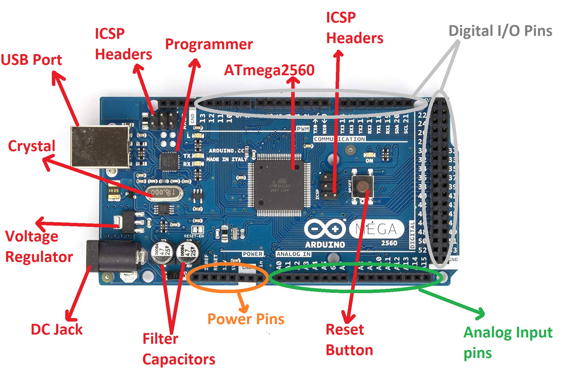
Pin Configuration of Arduino Mega
Digital I/O Pin: D0-D53
Analog Input Pins: A0-A15
PWM Pins: 2 – 13, 44 – 46
I2C pins: SDA(20), SCL(21)
SPI pins: 50 (MISO), 51 (MOSI), 52 (SCK), 53 (SS)
UART Pins:
- TX0-D0, RX0- D1
- TX1-D19, RX1- D18
- TX2-D16, RX2-D17
- TX3-D14, RX3-D15
Features of Arduino Mega
- Operating Voltage: 5V
- Input Voltage: 6-20V
- Operating Current:
- Output Voltage: 3.3V and 5V
- Output Current: 20mA(5V) and 50mA(3.3V)
- Digital I/O pins: 54
- ADC pins: 16
- PWM pins: 15
- UART: 4
Components required for this project
- Arduino Mega – 1
- LEDs (Any Color)- 125
- Resistor 220 ohm- 30
- Jumper wires
- Soldering wire
- Soldering Iron
Working of the project
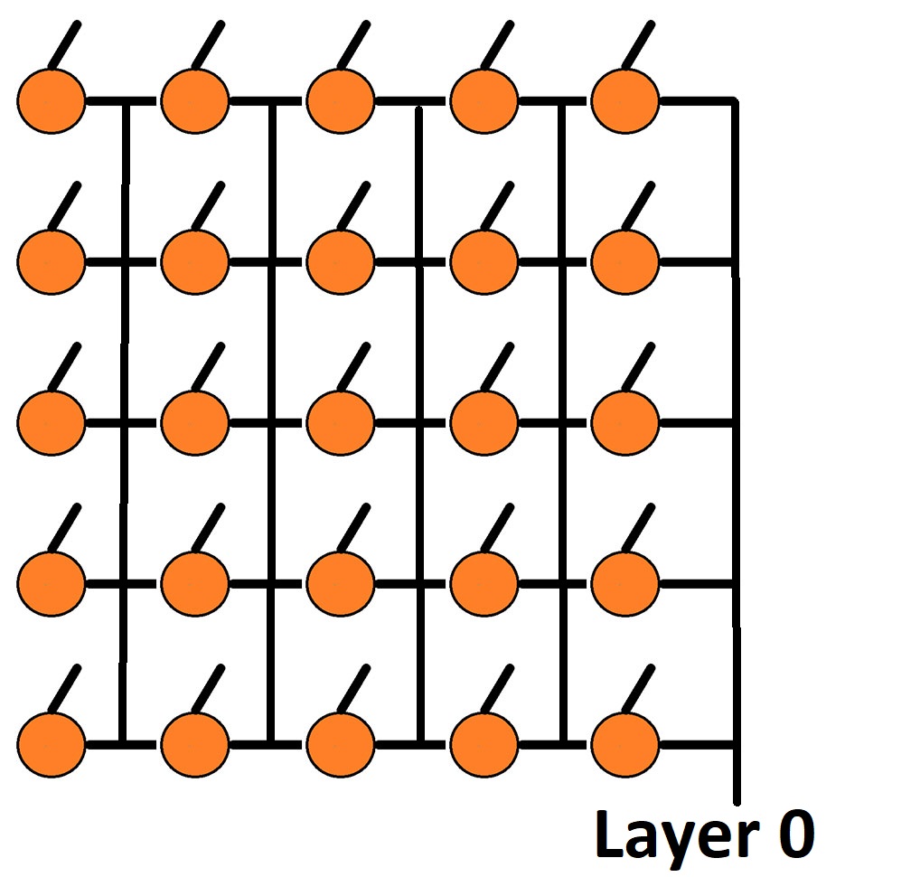
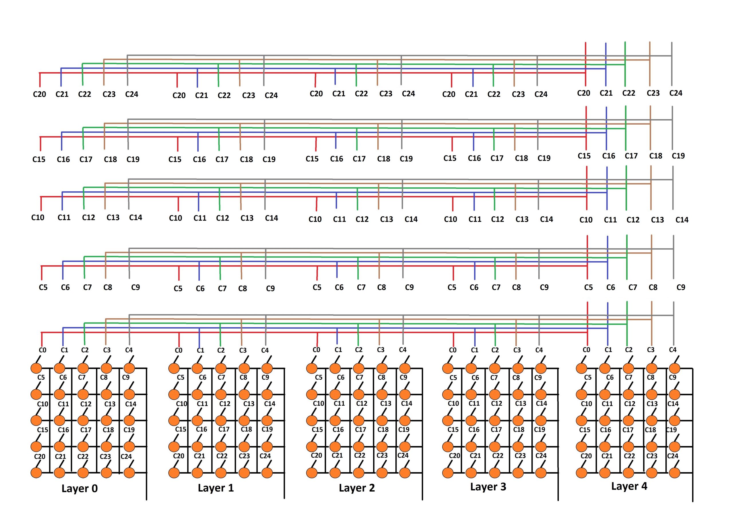
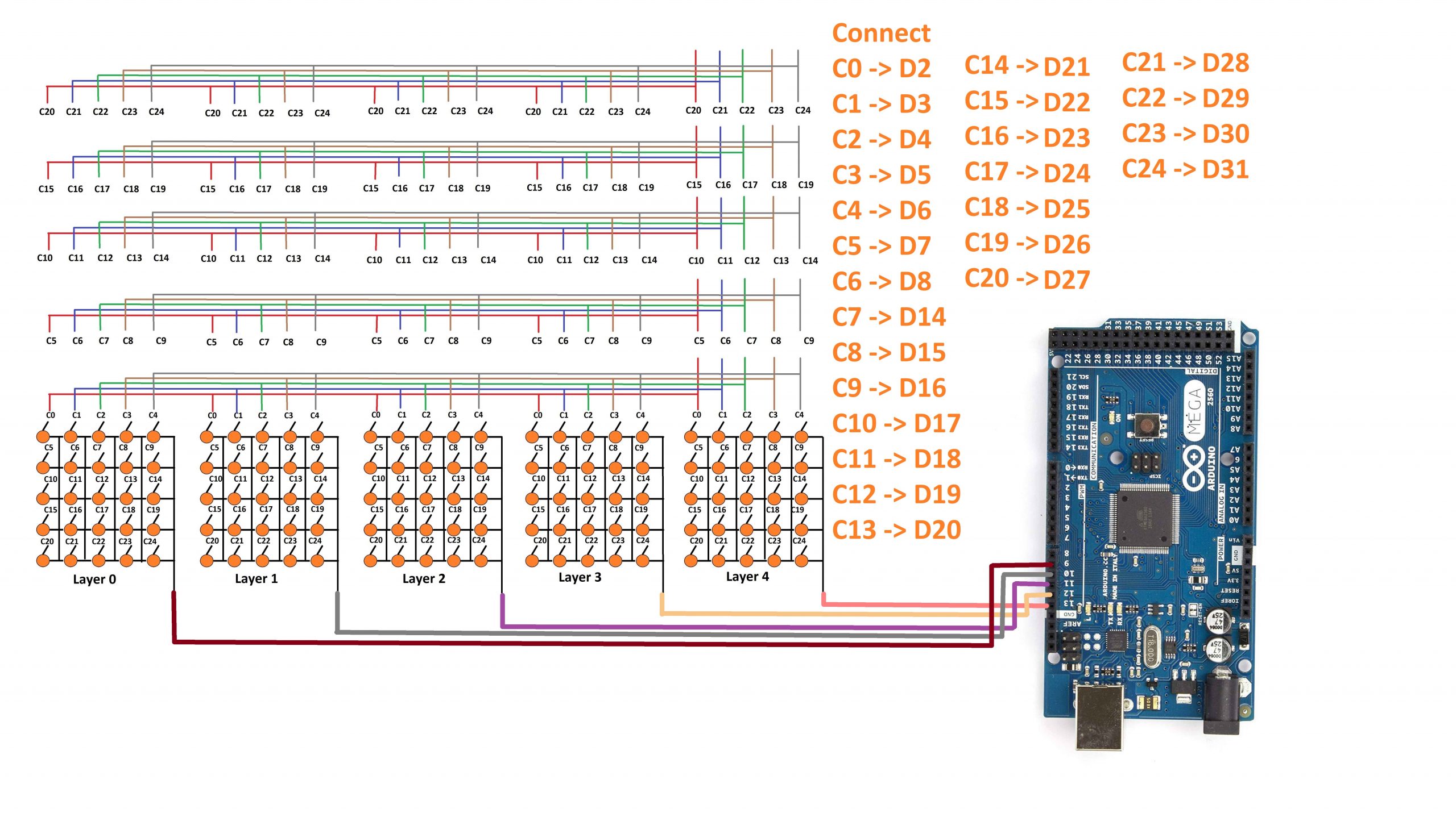
This LED cube consists of a total of 125 LEDs. We will control each LED with the help of an Arduino Mega board. For controlling all the LED present in the LED cube, we have divided this cube into 5 layers and 25 columns. The layers are layer0, layer1, layer2, layer3, and layer 4. Each layer consists of 25 LEDs and the negative terminal of all the LEDs present in a particular layer are connected to each other. Similarly, all the other layer consists the same number of LEDs and the negative terminal of all the LEDs are connected to each other.

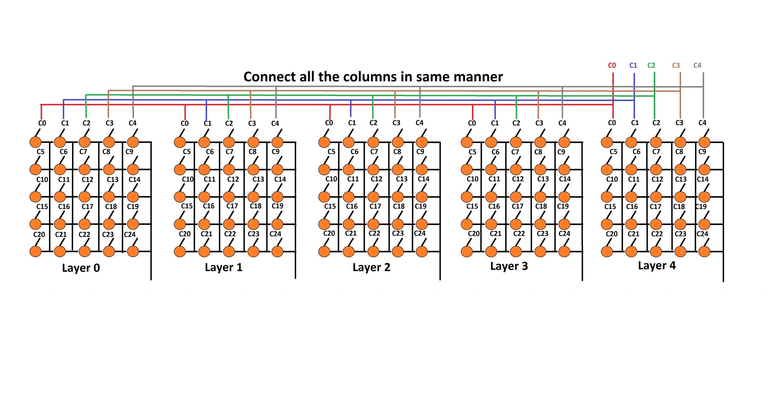
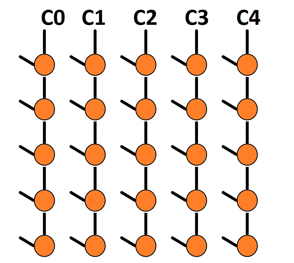
Then we have 25 columns starting from c0, c2, c3, c4, c5………..c24. Column c0 consists of LED from layer0, layer1, layer2, layer3, and layer4, and the positive terminal of all these LEDs are connected to each other. Similarly, all the other columns are connected in the same manner.

So, each LED has a unique position in the LED cube that can be specified by the layer and column number. Like, the first LED of the cube is (layer0,c0). similarly 2nd LED of the cube is (layer0,c1) and so on.
Suppose if you want to turn ON the first LED then you have to connect the layer0 to the GND and c0 to the 5V. Similarly, if you want to turn on the last LED then you have to connect the layer4 to the GND and c24 to the 5V. Likewise, you can turn ON and OFF all the LEDs.
Follow the following steps for making a 5x5x5 LED cube
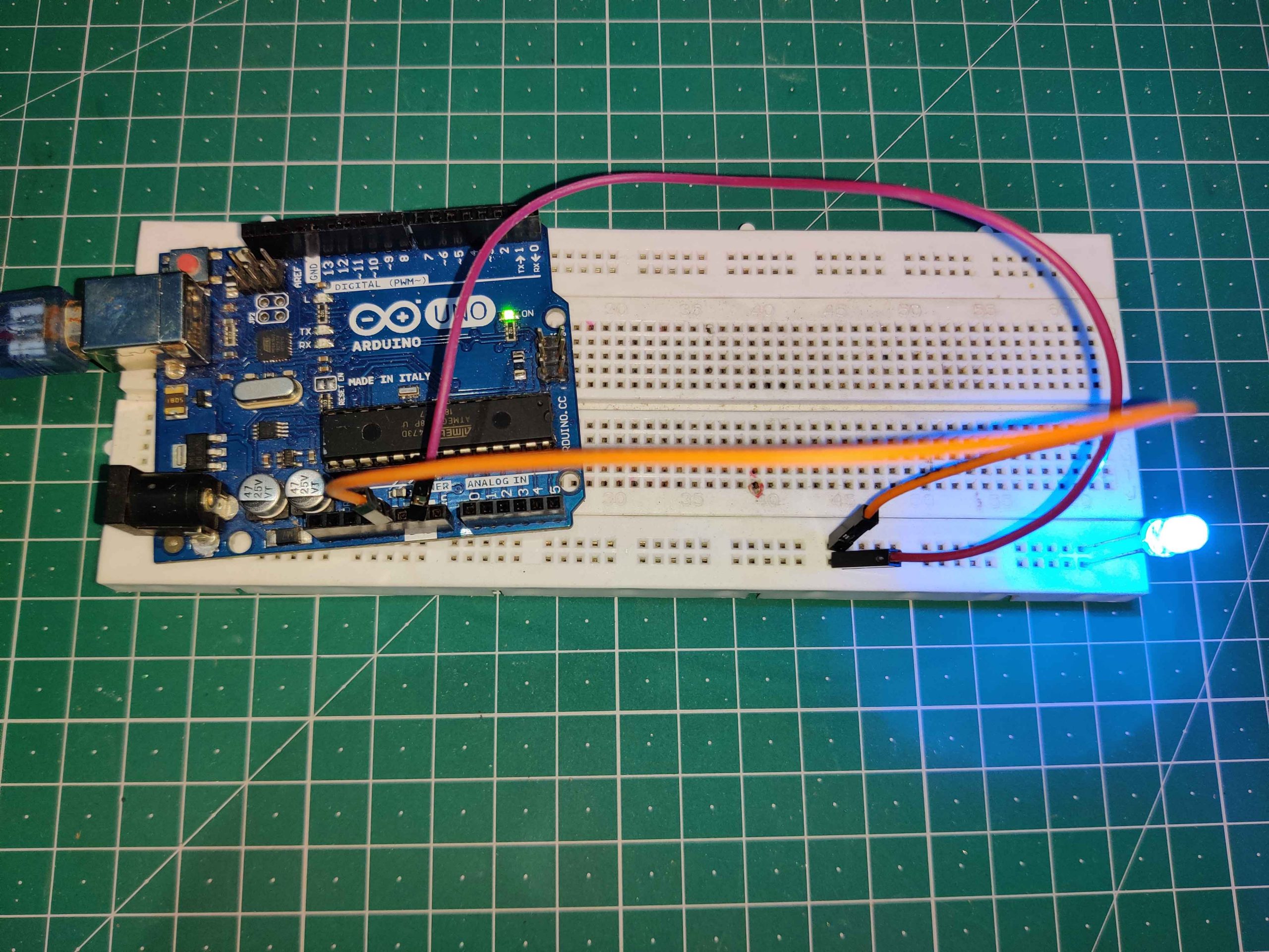
Step1: Test all the LEDs one by one and make sure all the LEDs are working. This is the most important step of all because it is really hard to replace the LED with the cube is finished. You can use a breadboard for this purpose as shown in the figure.
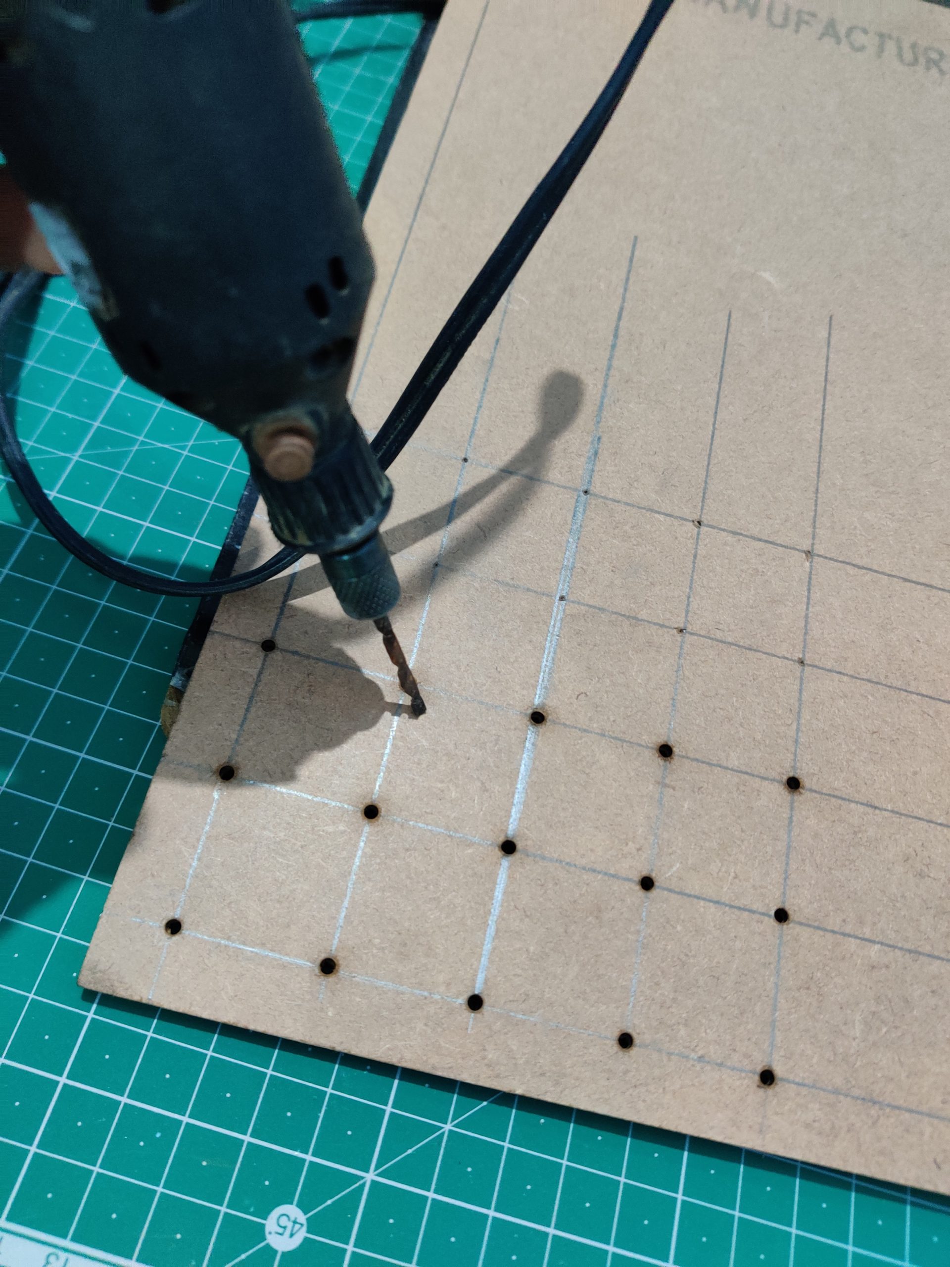
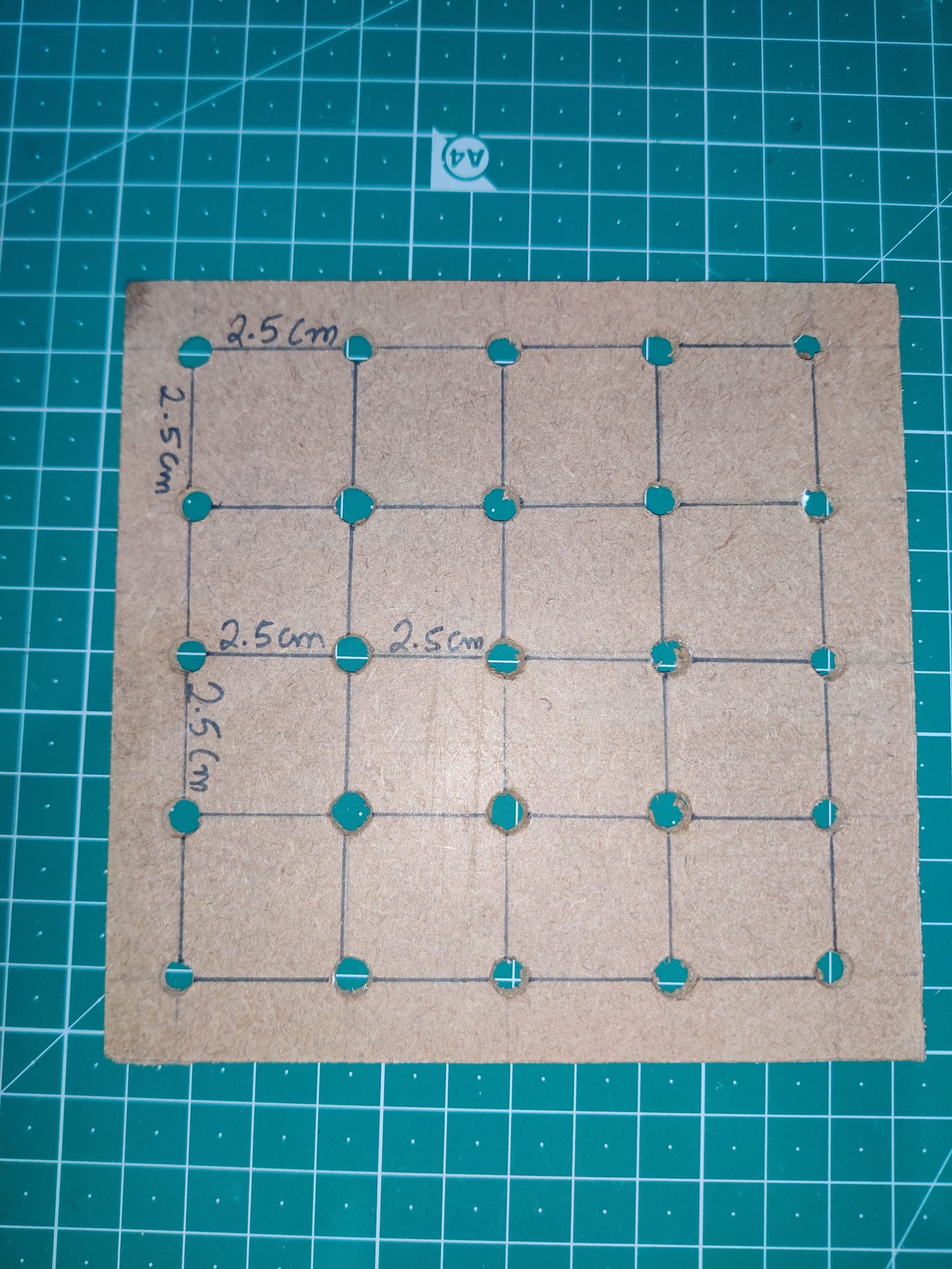
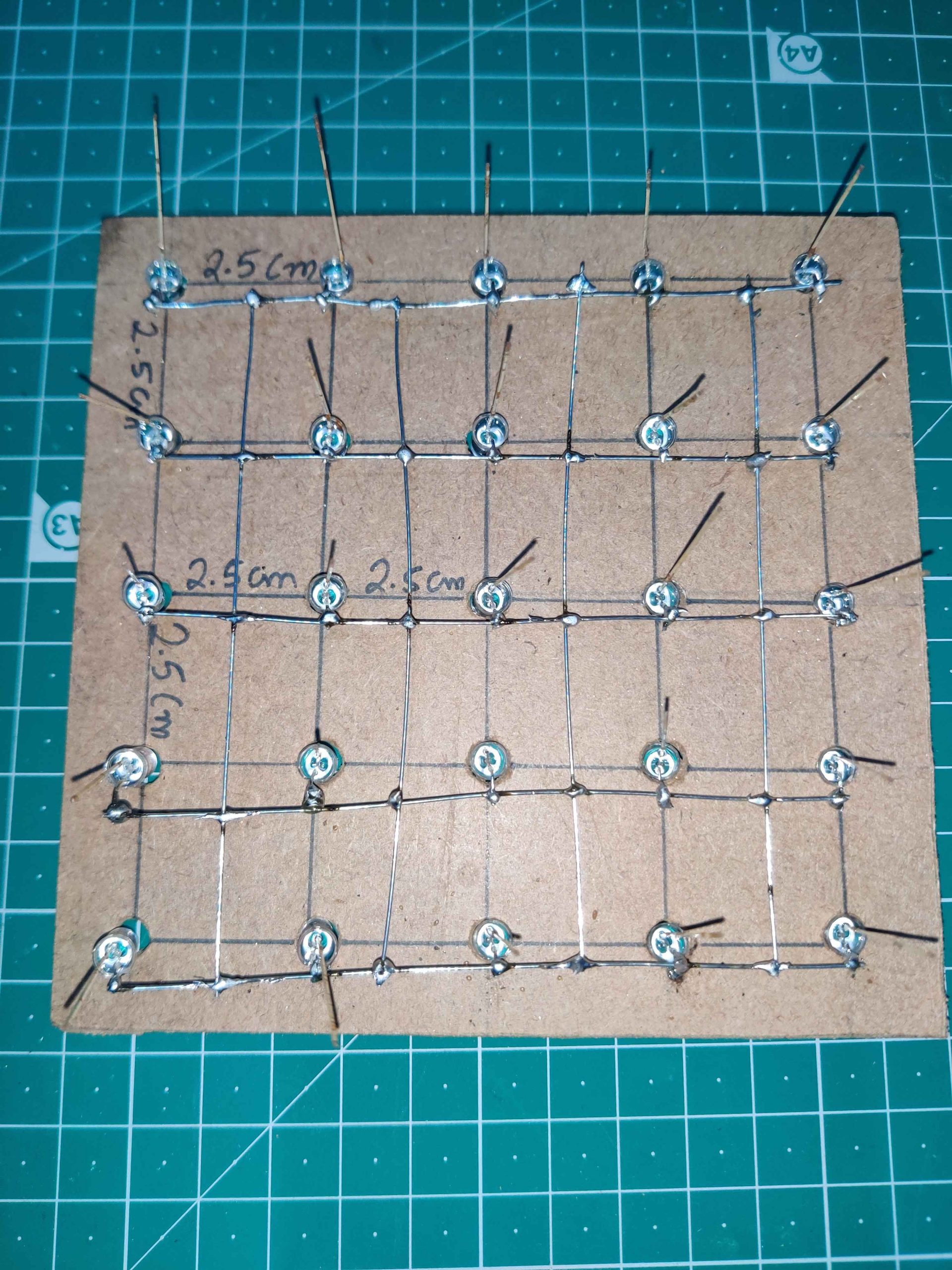
Step2: Take a cardboard nd make 125 holes as shown in the picture. You can use a drill machine for this purpose. The hole should of 5mm in diameter.
Step3: Bent the negative terminal of all the LEDs as shown in the picture.
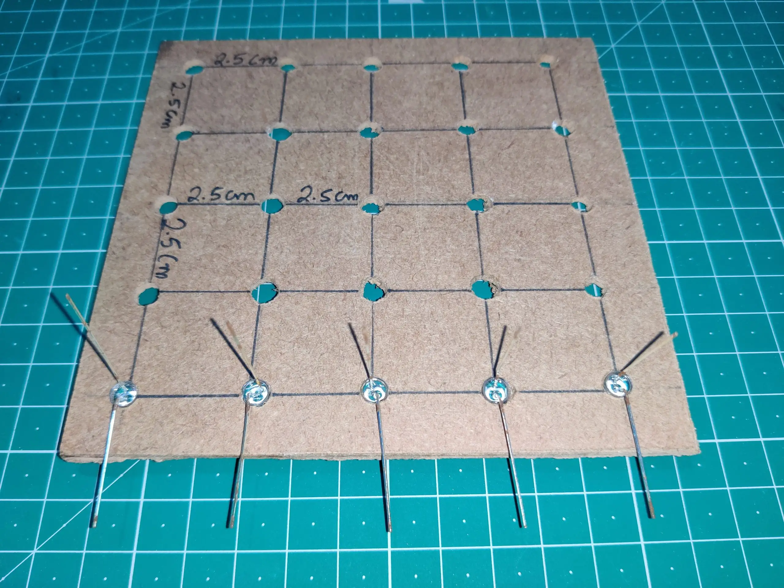
Step4: Insert all the 25 LEDs into the hole.

Step5: Solder negative terminal of all the LEDs present in the first row.
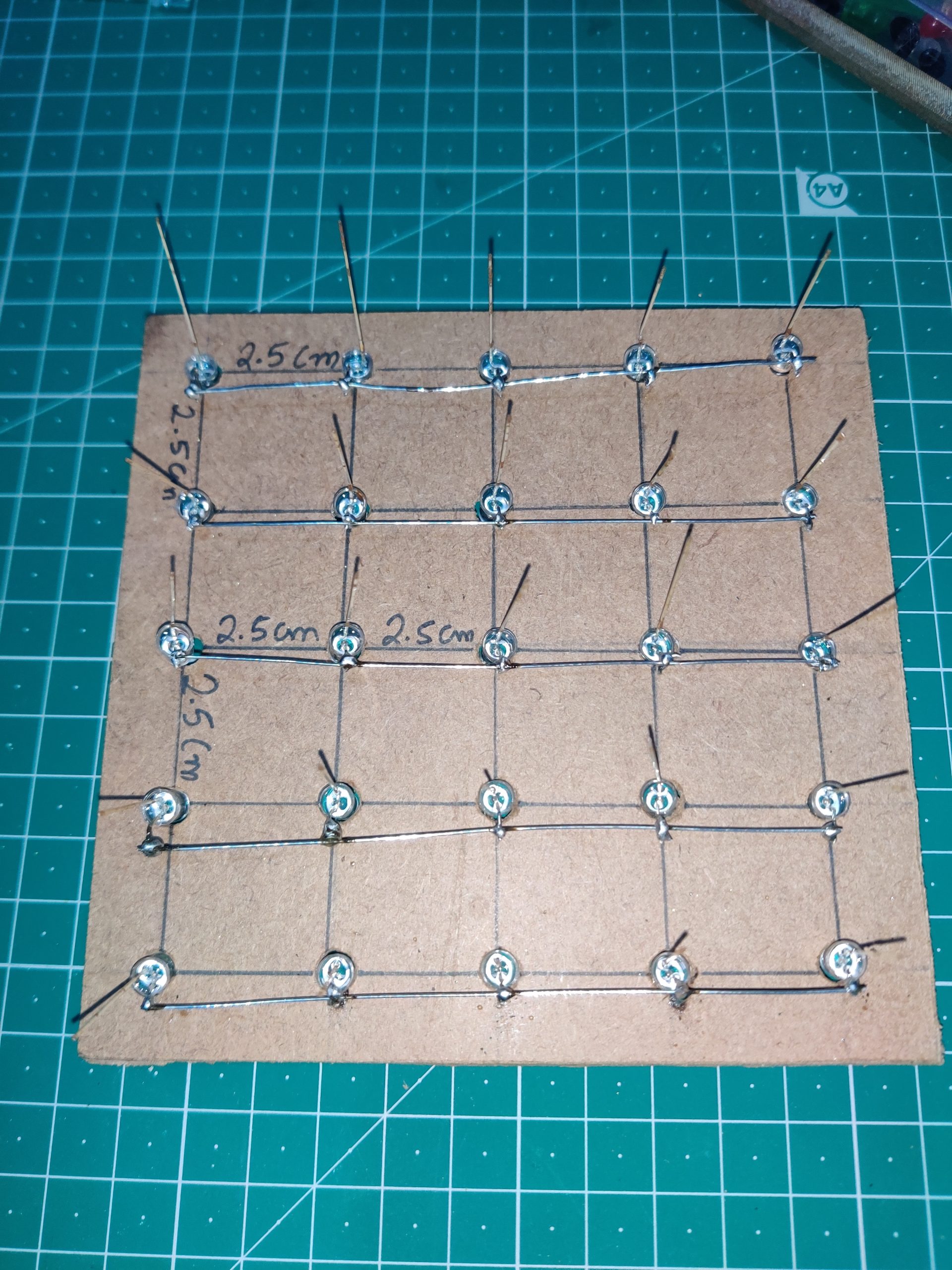
Step6: Solder all the other rows in the same manner.

Step7: Now, connect all the rows using a silver wire.
Step8: You have to create four more layers like this. In total we need five layers.
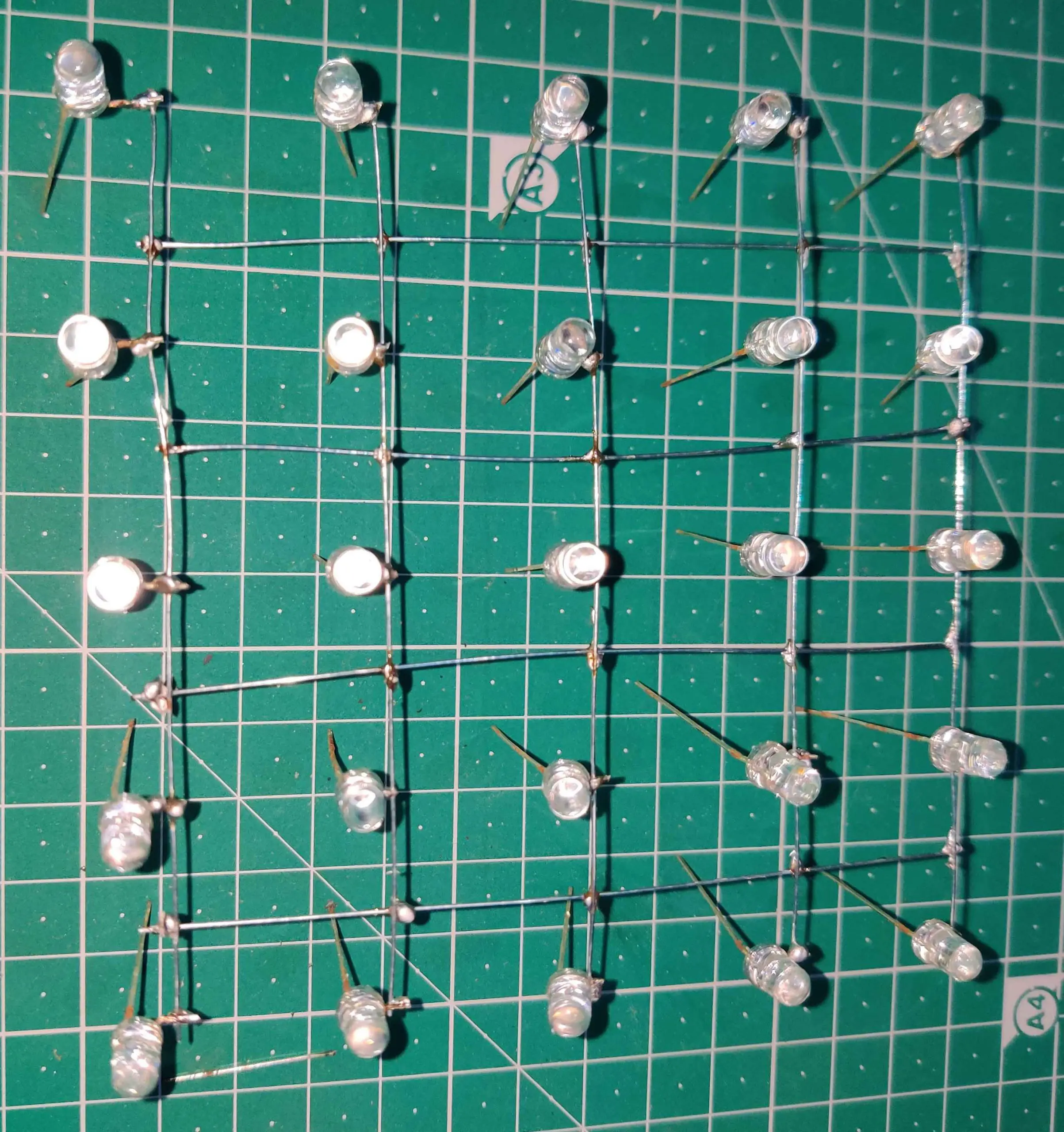
Step9: Connect all the columns one by one. You can place a carboard piece between the layer for easy soldering. Remember that there are 25 columns.
Step10: After connecting all the columns and layers, you will get 5 layers and 25 columns.
Step11: Connect all the layers and columns to the Arduino Mega Board
Step12: Upload the code to the Arduino Mega Board
int layerPin[5]={13,12,11,10,9};
int columnPin[25]={2,3,4,5,6,7,8,14,15,16,17,18,19,21,22,23,24,25,26,27,28,29,30,31};


void setup() {

for(int i=0;i<5;i++)
{
  pinMode(layerPin[i],OUTPUT);
}
for(int i=0;i<25;i++)
{
  pinMode(columnPin[i],OUTPUT);
}
for(int i=0;i<5;i++)
{
  digitalWrite(layerPin[i],HIGH);
}

}

void loop() {
animation1();
clearPin();
animation2();
}

void clearPin()
{
  for(int i=0;i<5;i++)
  {
    digitalWrite(layerPin[i],HIGH);
  }
  for(int i=0;i<25;i++)
  {
    digitalWrite(columnPin[i],LOW);
  }
}

void animation1()
{
  for(int i=0;i<25;i++)
  {
    digitalWrite(columnPin[i],HIGH);
    for(int y=0;y<5;y++)
    {
      digitalWrite(layerPin[i],LOW);
      delay(1000);
      digitalWrite(layerPin[i],HIGH);
      delay(1000);
    }
    digitalWrite(columnPin[i],LOW);
  }
}

void animation2()
{
  for(int i=0;i<5;i++)
  {
    digitalWrite(layerPin[i],LOW);
    for(int y=0;y<25;y++)
    {
      digitalWrite(columnPin[i],HIGH);
    }
    delay(1000);
    for(int y=0;y<25;y++)
    {
      digitalWrite(columnPin[i],LOW);
    }
    delay(1000);
    digitalWrite(layerPin[i],HIGH);
  }
}
Working of code
Define all the layer pins first. For that I have created an array named layerPin and stored all the pin number inside it.
int layerPin[5]={13,12,11,10,9};Define all the pins for columns. For that, I have created an array named columnPin and stored all the pin numbers inside it.
int columnPin[25]={2,3,4,5,6,7,8,14,15,16,17,18,19,21,22,23,24,25,26,27,28,29,30,31};Inside the void setup(), first set all the layer pin as OUTPUT uisng a for loop.
void setup() {

for(int i=0;i<5;i++)
{
  pinMode(layerPin[i],OUTPUT);
}
Similarly, set all the column pin as OUTPUT using a for loop.
for(int i=0;i<25;i++)
{
  pinMode(columnPin[i],OUTPUT);
}
Set all the layer pins as HIGH because when you use the pinMode() function, by default all the pins are set to LOW. We have connected the negative terminal of all the LEDs to these layer pins. So, we have to make them HIGH.
for(int i=0;i<5;i++)
{
  digitalWrite(layerPin[i],HIGH);
}
This is a function to set all the columns and layer pins to default state. The layer pins must be set to HIGH and column pins must be set to LOW in order to turn OFF the LED. This function will help in moving from one pattern to another.
void clearPin()
{
  for(int i=0;i<5;i++)
  {
    digitalWrite(layerPin[i],HIGH);
  }
  for(int i=0;i<25;i++)
  {
    digitalWrite(columnPin[i],LOW);
  }
}
This is another function, I have created this for generating the first animation. In this animation all the LEDs will turn ON and OFF one by one.
void animation1()
{
  for(int i=0;i<25;i++)
  {
    digitalWrite(columnPin[i],HIGH);
    for(int y=0;y<5;y++)
    {
      digitalWrite(layerPin[i],LOW);
      delay(1000);
      digitalWrite(layerPin[i],HIGH);
      delay(1000);
    }
    digitalWrite(columnPin[i],LOW);
  }
}
This function is for second animation. In this animation the Layer will turn on and OFF one by one. This is how you can create any animation you want using this LED cube.
void animation2()
{
  for(int i=0;i<5;i++)
  {
    digitalWrite(layerPin[i],LOW);
    for(int y=0;y<25;y++)
    {
      digitalWrite(columnPin[i],HIGH);
    }
    delay(1000);
    for(int y=0;y<25;y++)
    {
      digitalWrite(columnPin[i],LOW);
    }
    delay(1000);
    digitalWrite(layerPin[i],HIGH);
  }
}
This is the main loop of this project. First, the animation1 will run. Then using the clearPin() function, we will clear all the pins. After that animation2 will run and these three functions will run again and again in a loop.
void loop() {
animation1();
clearPin();
animation2();
}
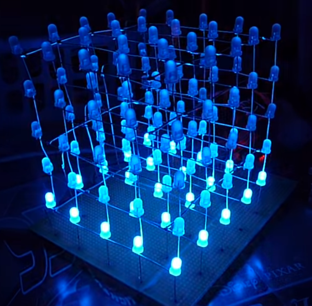
Output Result
Comments are closed.