In this tutorial, you will learn how to upload a bootloader in a newly purchased ATmega328P IC, and upload code in ATmega328P, ATtiny85, and ATmega8 using Arduino UNO board.
In some Arduino projects, you may only want to use the microcontroller IC(ATmega328P) instead of using the whole Arduino UNO board. In that case either you can remove the ATmega328P IC from the Arduino UNO board and use it with a minimal circuit or you can buy a new ATmega328P IC and upload code in it and use it in your project.
While some of the Arduino projects do not require a powerful microcontroller like ATmega328P so, at that time instated of using the Arduino UNO board or ATmega328P IC, you can use ATtiny85. In this tutorial, you will learn all these things.
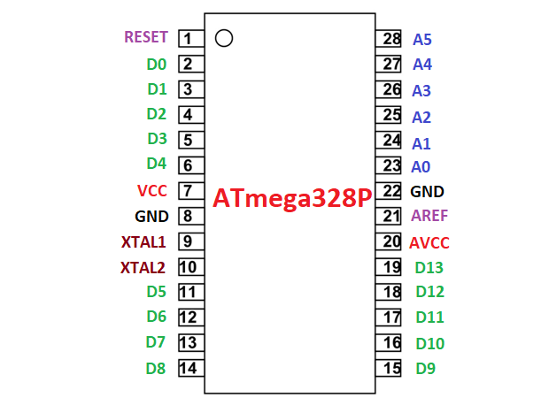
Pin configuration of ATmega328P IC
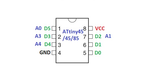
Pin configuration of ATtiny25/45/85
ATmega328P on a breadboard or standalone ATmega328P
Here, we will use the same ATmega328P IC that is present in the Arduino UNO board.
Step1: Upload your code to the Arduino Board. I have uploaded an LED blinking code in my case.
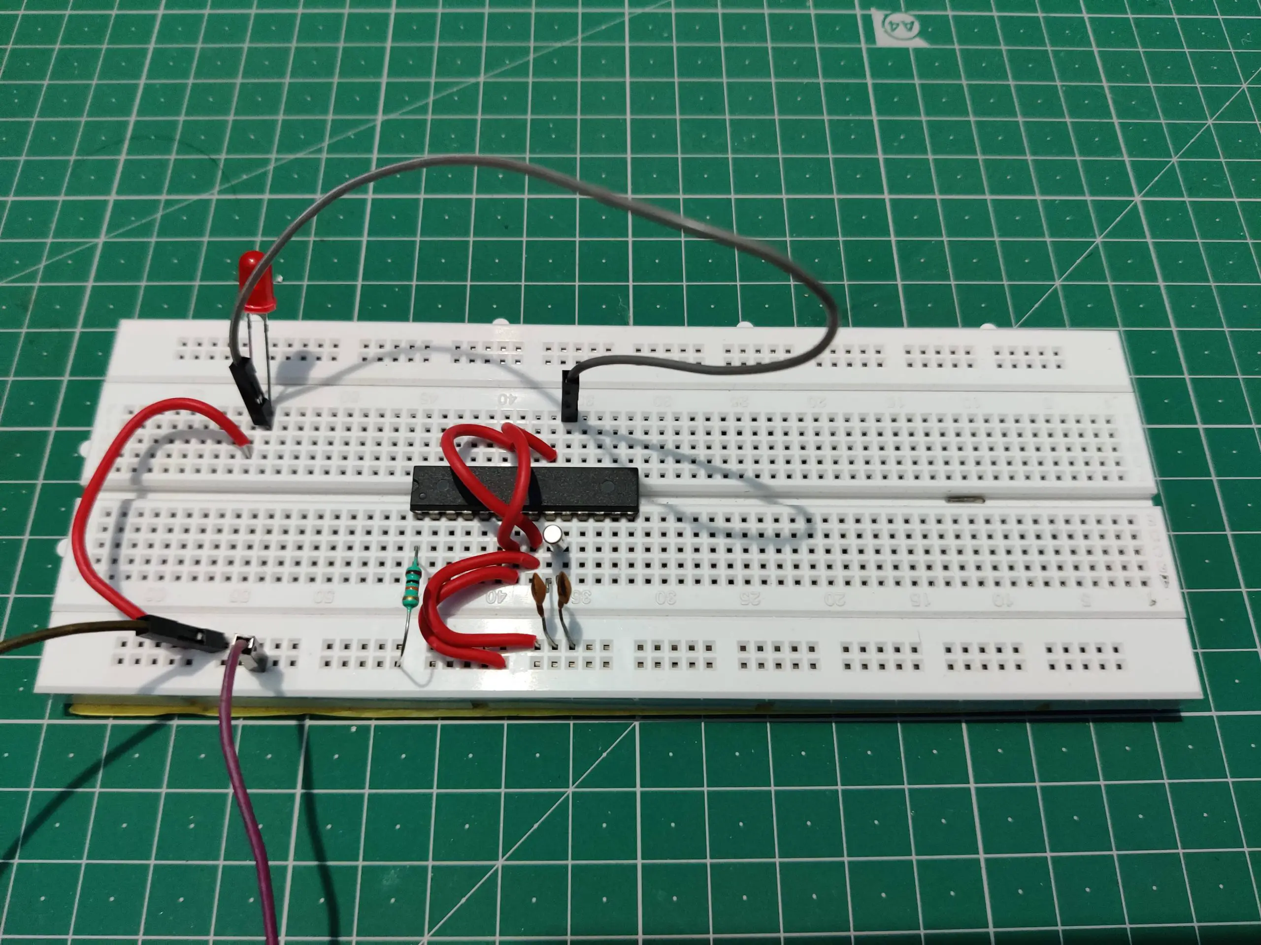
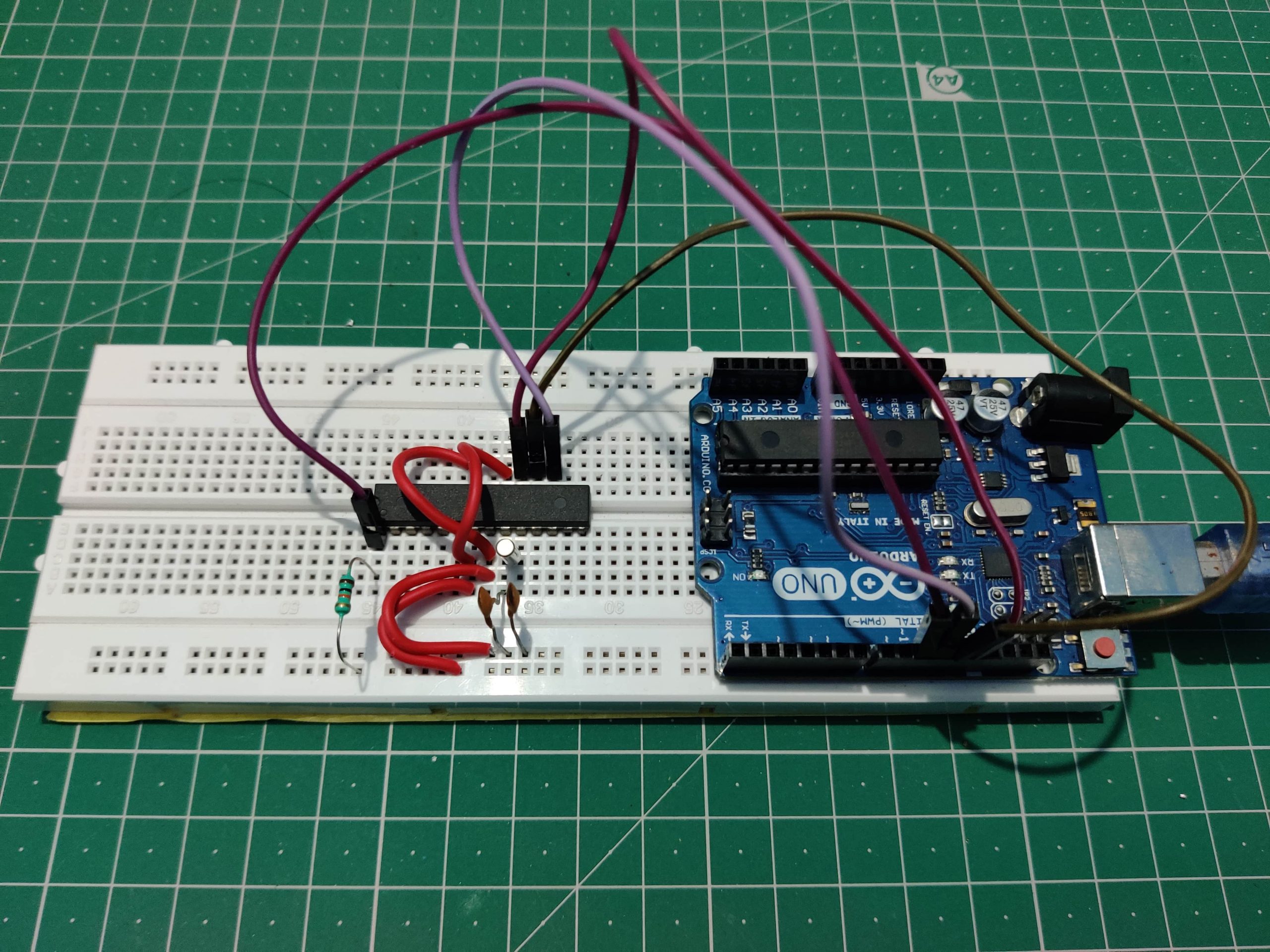
Step3: Remove the ATmega328P from the Arduino UNO board and insert it onto the breadboard.
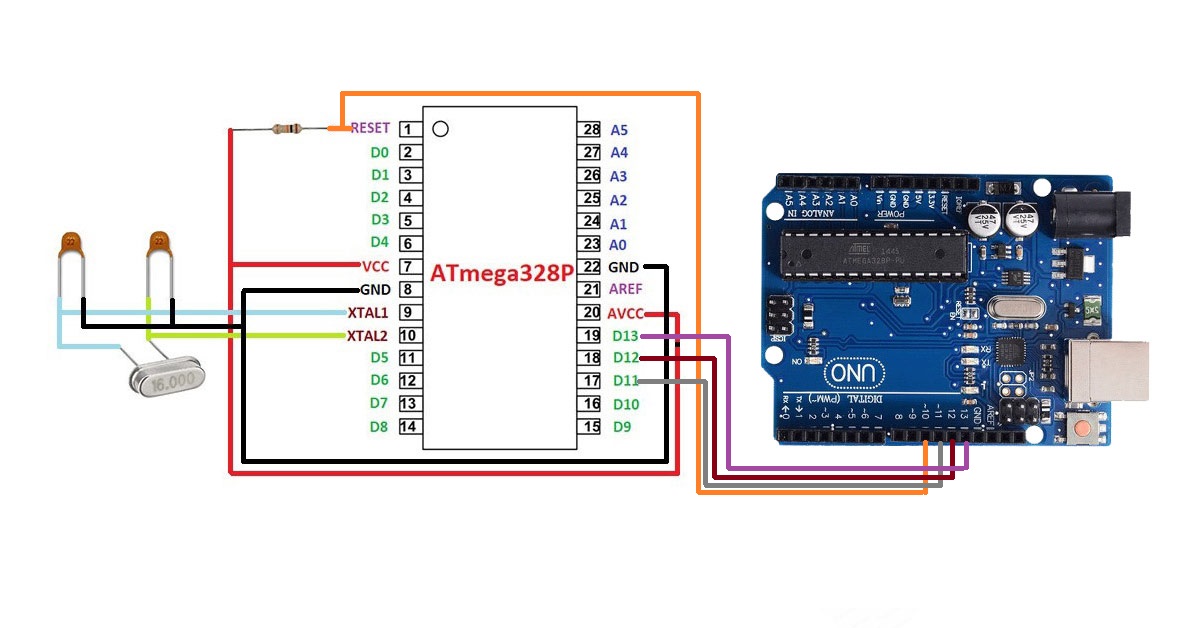
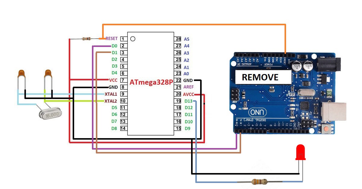
Step2: Create a minimal circuit that is required for ATmega328P IC. Refer to figure 1.3.
Step3: Connect all your modules or sensor or any electronic components to the ATmega328P IC that you want to use in your project. I am creating a LED blink project so, I have connected an LED on the D3 pin of the ATmega328P. See figure 1.4. The pins marked on the Arduino UNO board are different on the ATmega328P IC. Refer to Figure 1.1 for pin configuration of ATmega328P IC.
Step4: Give power to the circuit using a 5V adapter.

Capacitors: 22pF Crystal: 16MHz
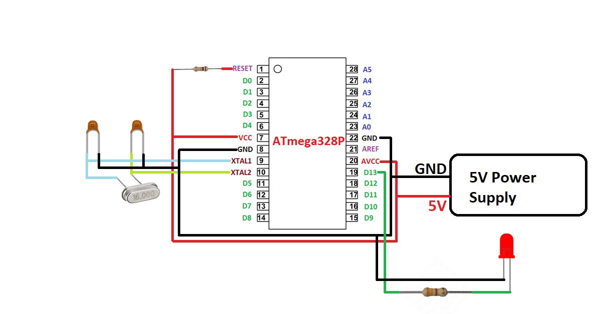
Capacitors: 22pF Crystal: 16MHz Resistor: 330 Ohm
Upload bootloader in ATmega328P IC
In case you want to use a new ATmega328P IC for your project then you have to follow the following steps.
Step1: Create a minimal circuit for the newly purchased ATmega328P IC as shown in figure 1.3.
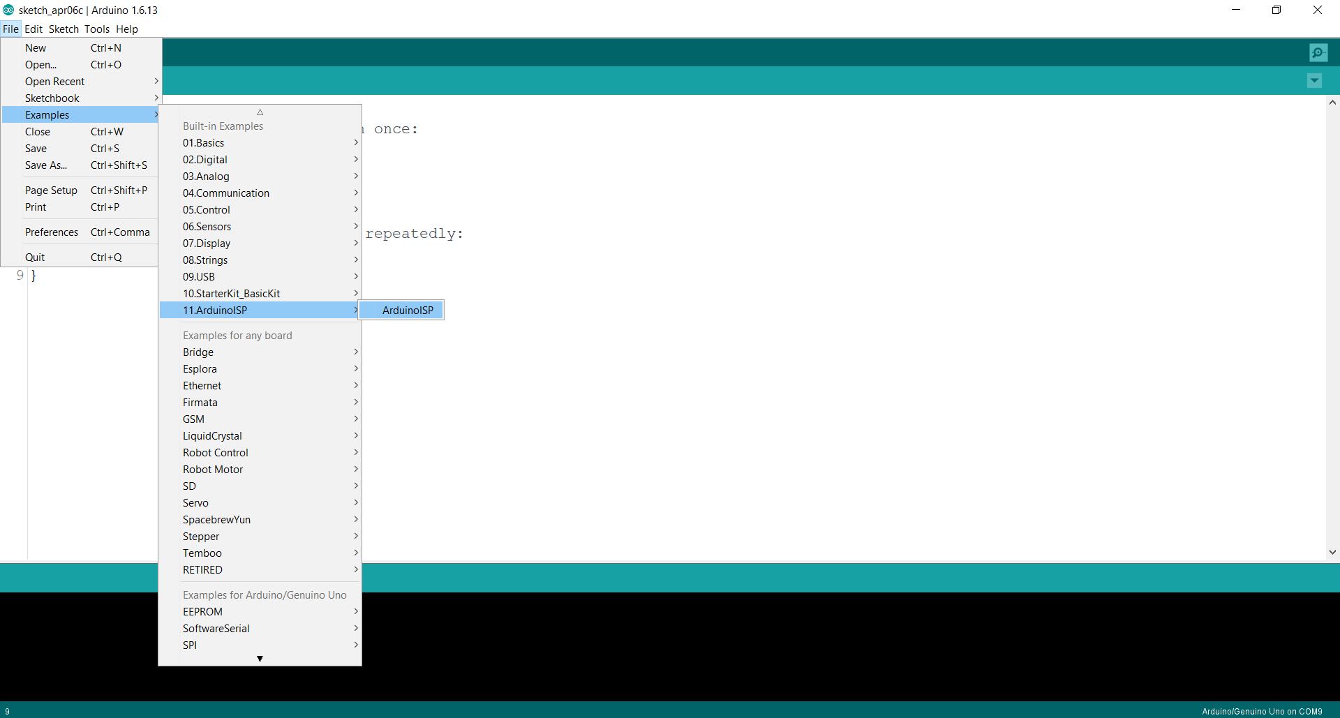
Step2: Go to the File tab then click on examples then click on ArduinoISP.
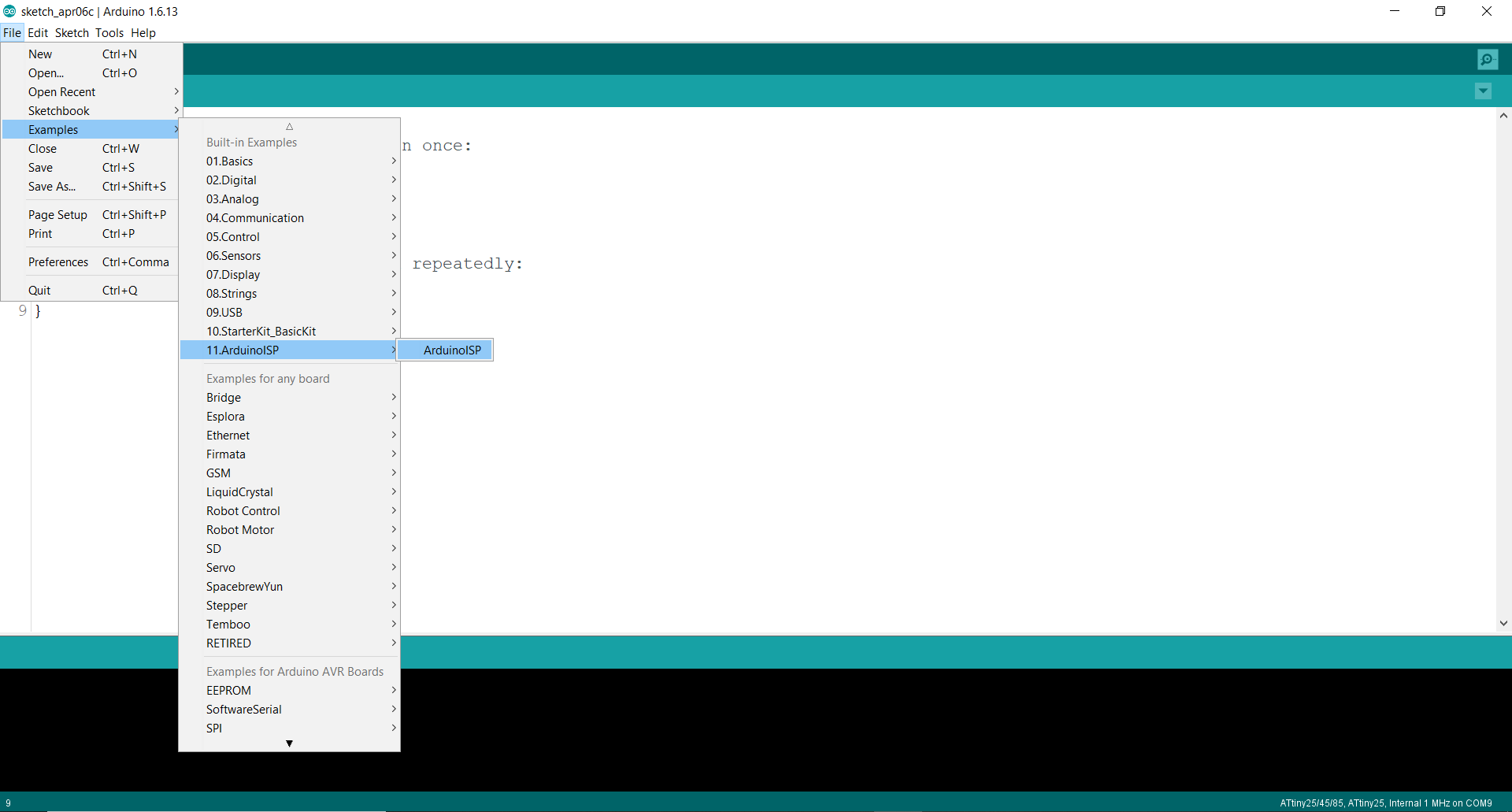
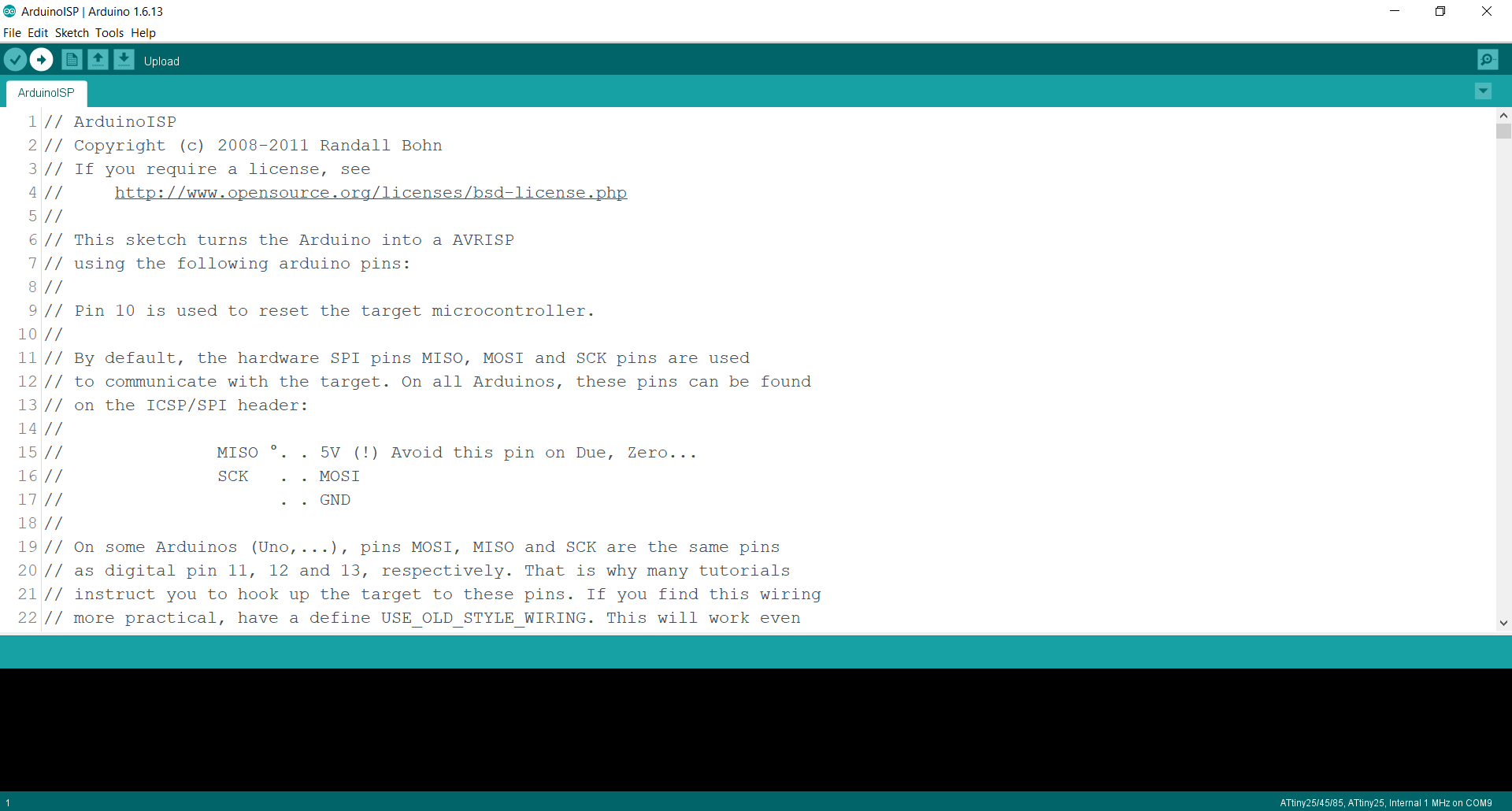
Step3: Upload this ArduinoISP code to your Arduino UNO Board.

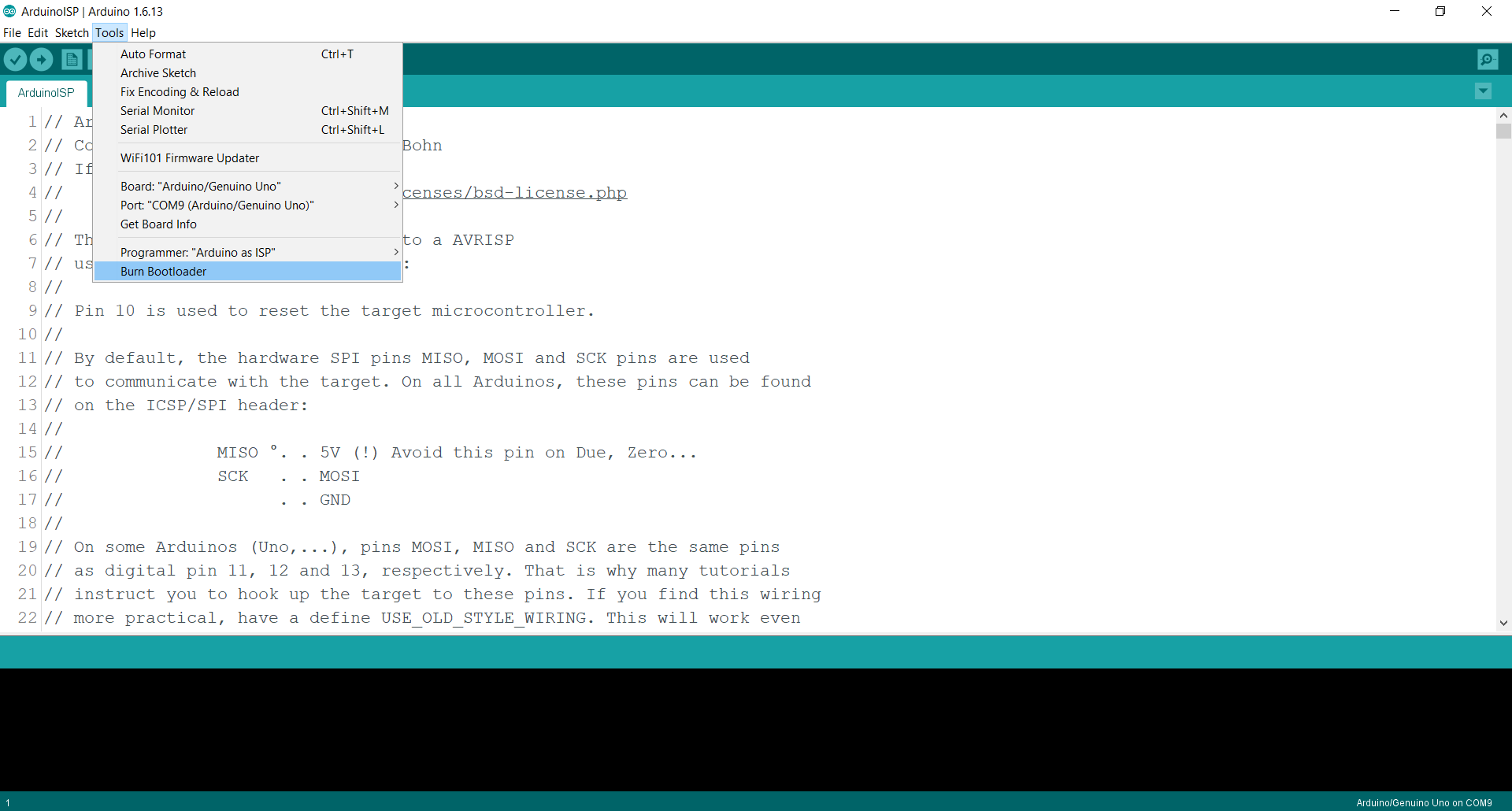
Step4: After the ArduinoISP code is uploaded, go to the Tools tab and then go to the Programmer option and select Arduino as ISP.

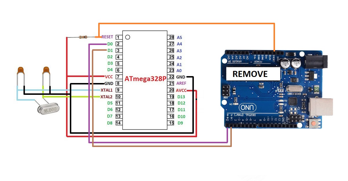
Step5: Connect the ATmega328P IC with the Arduino UNO board as shown in Figure 1.4.
Step6: Go to the Tools tab again and then click on burn bootloader.
Step7: The bootloader is burned in the IC. Now, you can use it to upload code in it. For that remove the main microcontroller IC from the Arduino UNO board and connect the new ATmega328P IC as shown in the figure.
Step8: Upload your code to the new IC. I am uploading an LED blinking code. Make sure you have selected the right port and board(Arduino UNO).
ATmega328P IC minimal circuit explanation
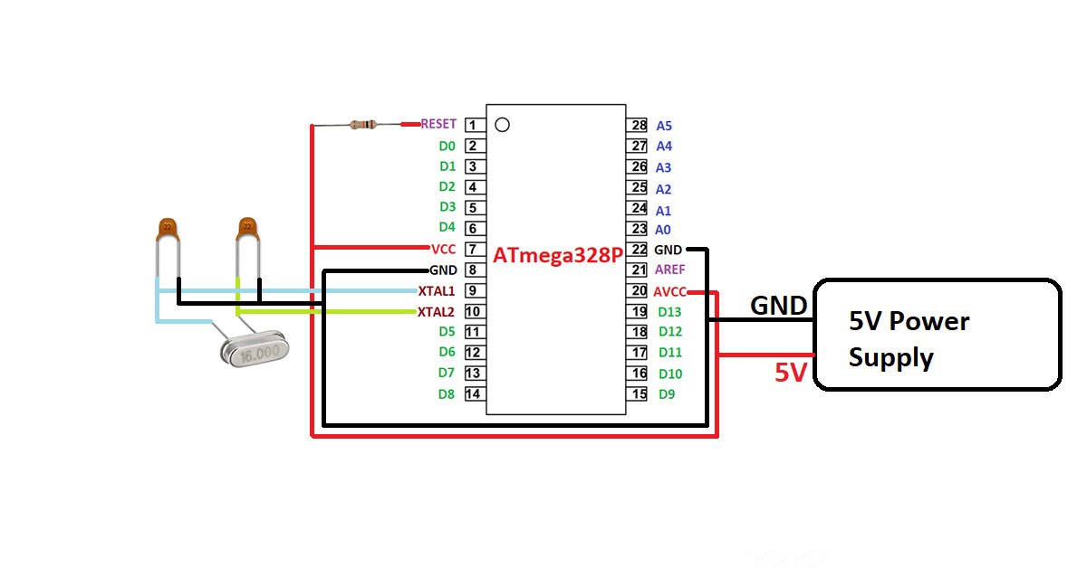
The circuit shown in the figure is the minimal circuit that is required to work with standalone ATmega328P IC.
Pin 1 is the RESET pin used for resetting the microcontroller. You have connect a pull-up resistor to this pin because the microcontroller resets when its get a logic LOW signal.
Pin 7 and Pin 20 are VCC pin you have to connect 5V here.
Pin 8 and Pin 22 are GND pin you have to connect GND here.
Pin 9 and Pin 10 are used for connecting external crystal of 16MHz along with two 22pF capacitor.
Programing ATtiny24/44/84/25/45/85 with Arduino UNO
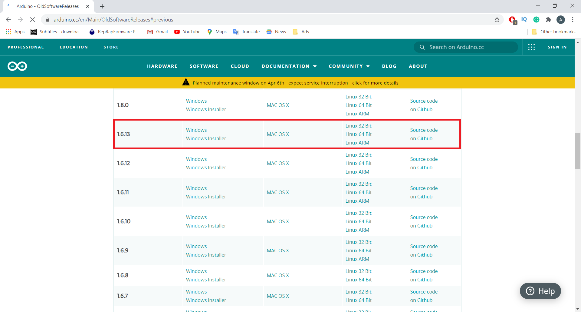
Setp1: Open Arduino.cc website and download Arduino 1.6.1. The newer versions will not work for this purpose.
Step2: Install Arduino 1.6.1 on your desktop/laptop.
Step2: Go to the File tab then click on examples and then click on ArduinoISP.
Step3: Upload this ArduinoISP code to your Arduino UNO Board.
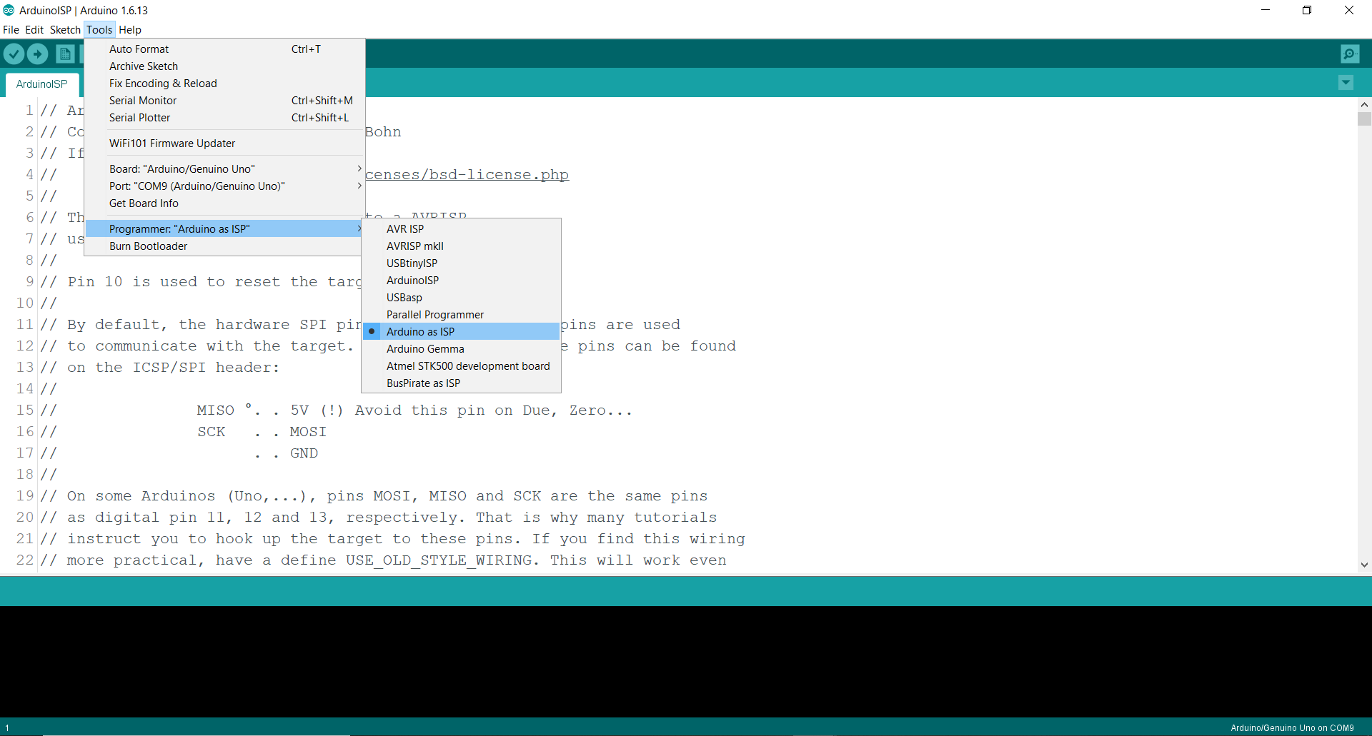
Step4: After the ArduinoISP code is uploaded, go to the Tools tab and then go to the Programmer option and select Arduino as ISP.

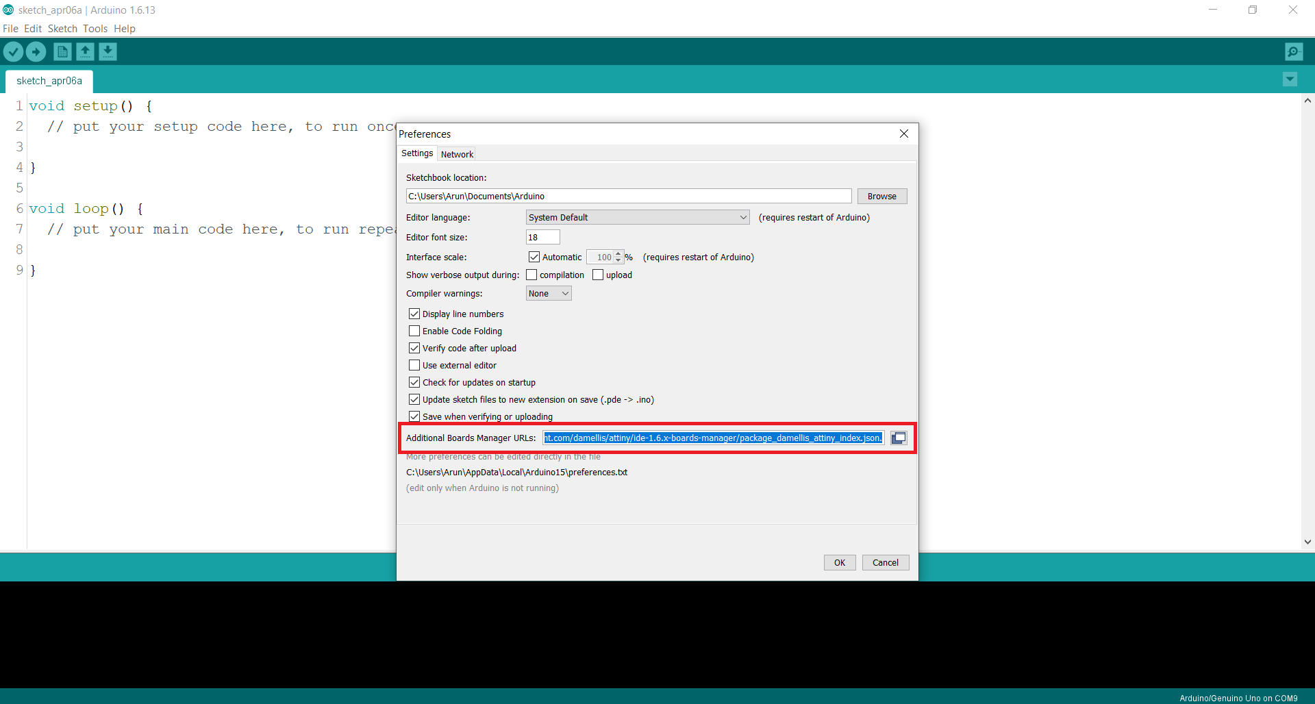
Step5: Go to the File tab, then click on preferences. Copy and paste this link in “Additional Board Manager URLs https://raw.githubusercontent.com/damellis/attiny/ide-1.6.x-boards-manager/package_damellis_attiny_index.json
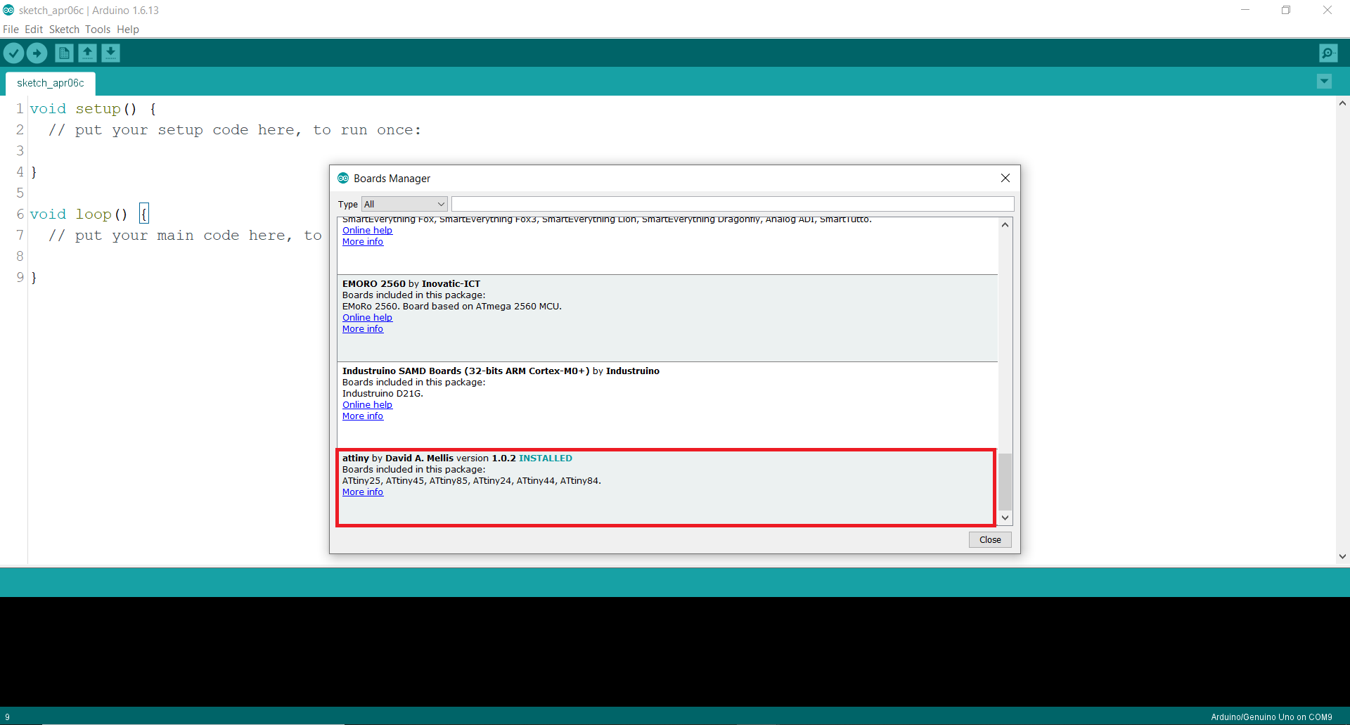
Step6: Go to the Tools tab then click on board then click on Board manager. The board manager will open.

Step7: Wait for some time and then scroll down. You will this option. Click on install.
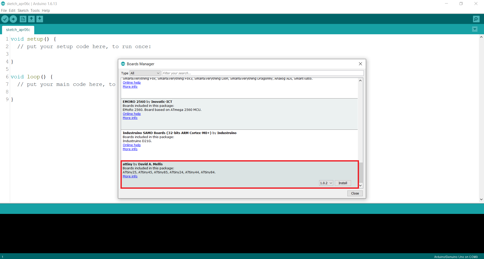
Step8. The boards are installed.
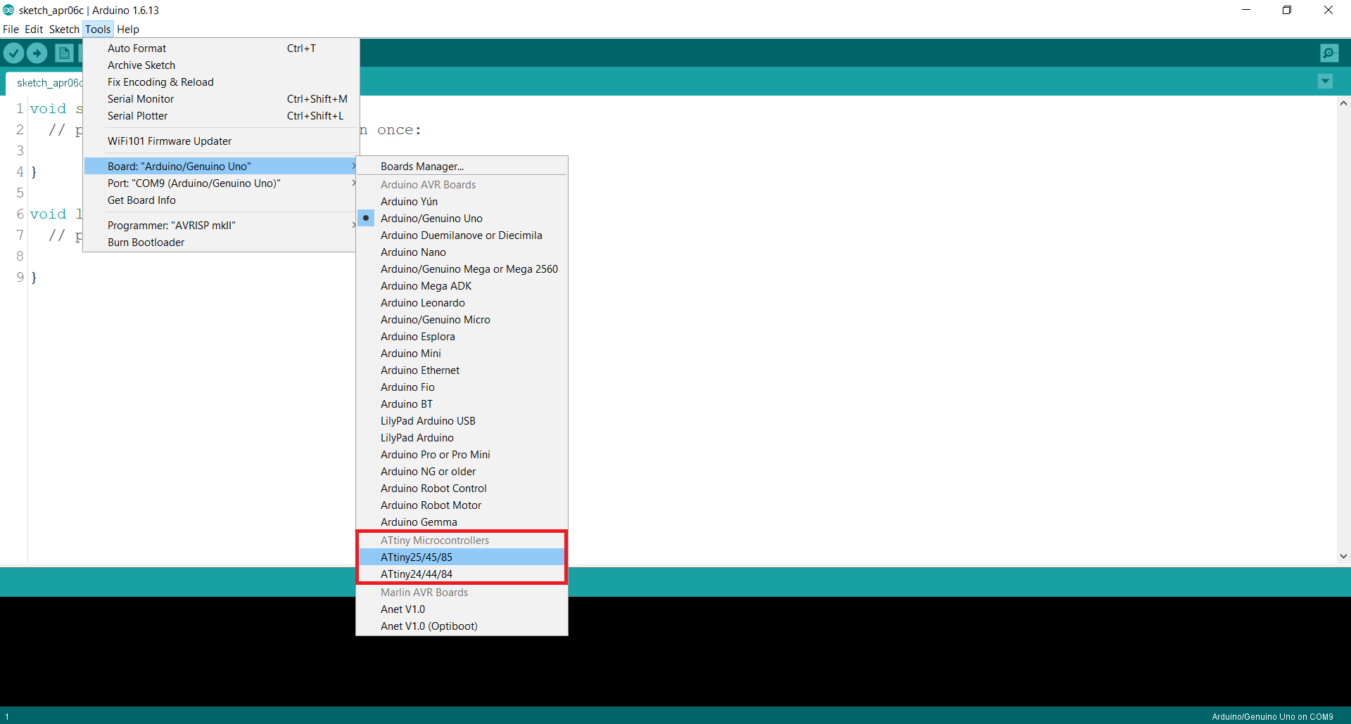
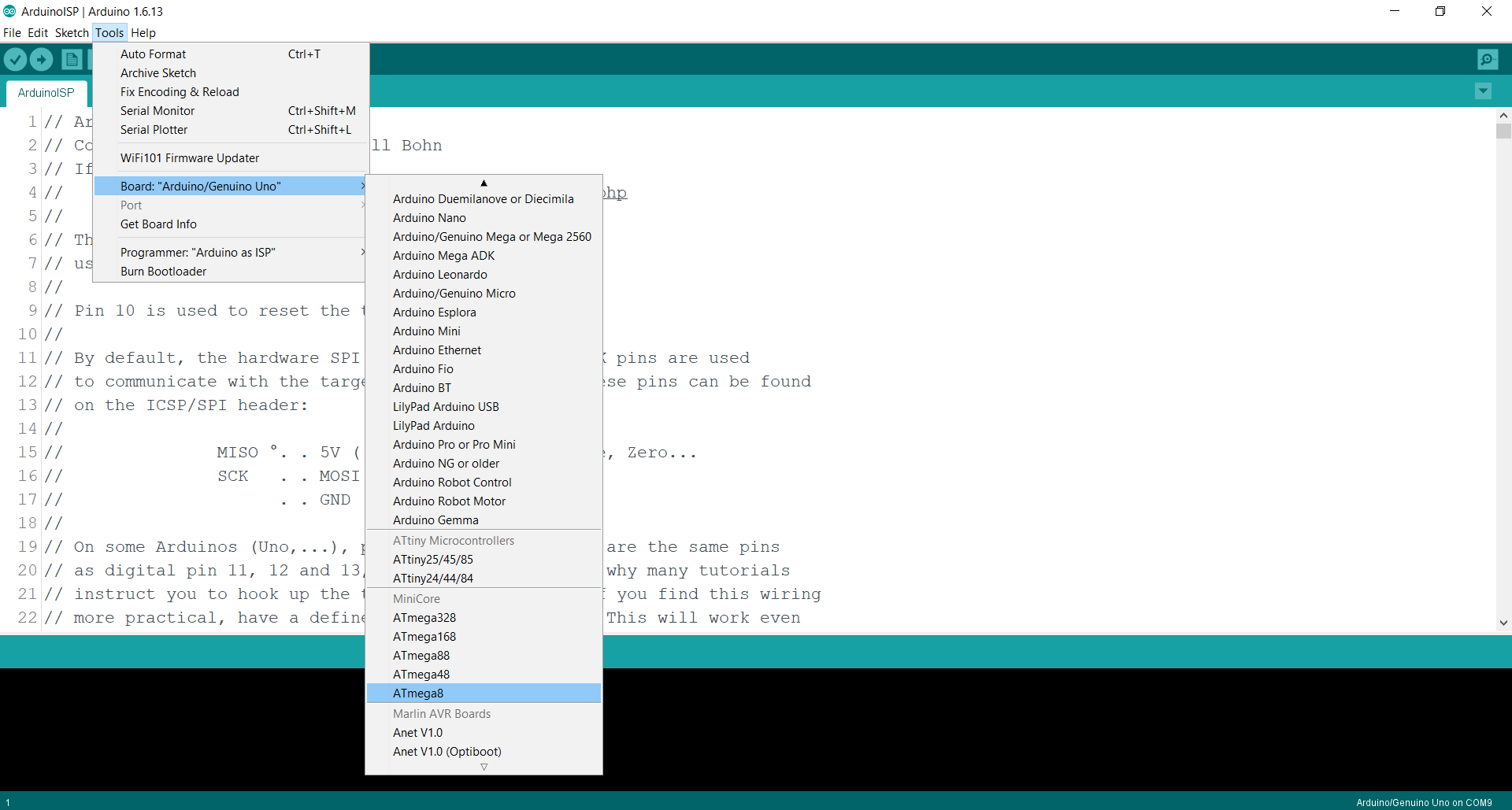
Step9: Go to the Tools tab again. Click on boards and you will see two more options. Select ATtiny25/45/85.
Step10: From the Tools tab set the Internal clock to 8MHz.

Step11: From the Tools tab select programmer Arduino as ISP
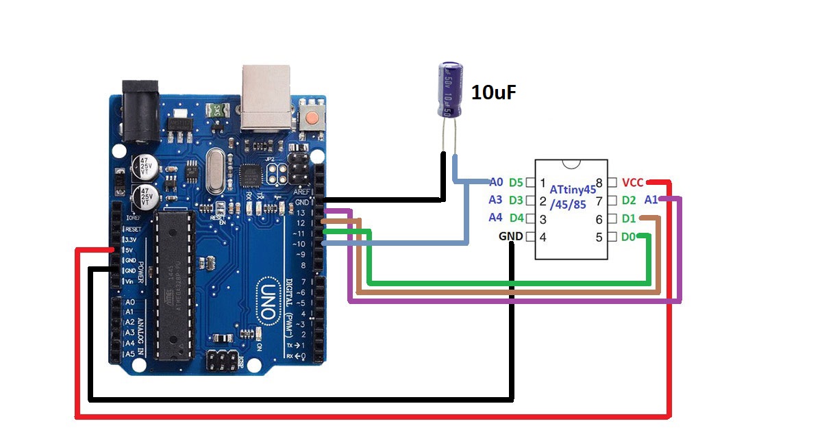
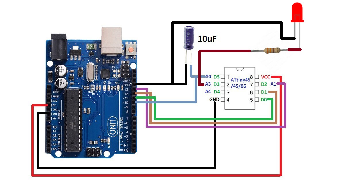
Step12: Connect the ATtiny85 IC to the Arduino UNO as shown in the figure 1.7
Step13.Upload your code to the new IC. I am uploading an LED blinking code. Make sure you have selected the right port and board(Arduino UNO).
Programming ATmega8 with Arduino UNO
You have to follow all the steps that you have followed for programming ATtiny IC with Arduino UNO board. The only difference is that you have to paste this link in the Additional Board URls and Install MiniCore from the board manager. https://mcudude.github.io/MiniCore/package_MCUdude_MiniCore_index.json
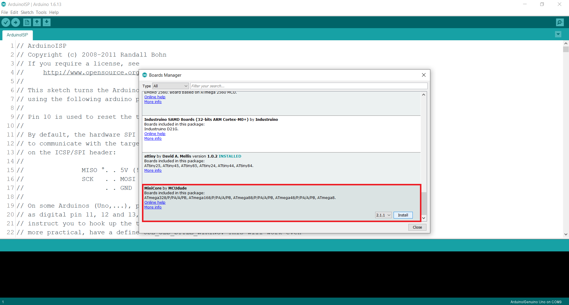
Then select ATmega8 from the board. Rest of the steps are same as that of the ATtiny
Comments are closed.