Interfacing gyroscope to arduino uno.
This article is about interfacing gyroscope to arduino. Gyroscope is a device used for measuring the angular velocity in the three axes. It works under the concepts of angular momentum and can be used to determine the orientation of an object. Typical applications of gyroscope includes missile guidance, flight control, smart phones, game station joy sticks etc. Mechanical gyroscopes, MEMS gyroscope, optic fiber gyroscope, ring laser gyroscope.
Here we deal with the MEMS gyroscope. MEMS is the abbreviation of micro electro mechanical system. The MEMS gyroscope works under the principle of Focault pendulum and has a vibrating electro mechanical element for sensing the orientation. MEMS gyroscopes are very compact and comparatively cheap. They are widely used in consumer products like smart phones, joysticks, RC toys etc.
GY521 module.
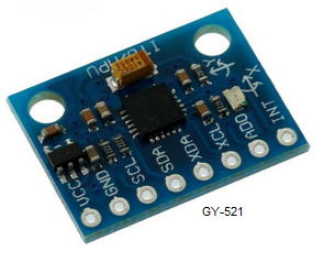
The gyroscope module used here is GY521. GY521 is a 3 axis gyroscope plus accelerometer module based on MEMS IC MPU6050. The MPU6050 has 6 built in 16 bit ADC channels, three for the gyroscope outputs and three for the accelerometer outputs. It communicates with the microcontroller using the I2C protocol. The operating voltage range of MCU6050 is from 2.37v to 3.46V. A low drop out regulator is provided on the GY521 board for providing this voltage. The full scale ranges of the acclelerometer and gyroscope are user programmable and they are +/- 2g, 4g, 8g and 16g for the accelerometer and +/- 250 °/S, 500 °/S, 1000 °/S and 2000 °/S. The photograph of a GY521 module is shown below.
v_pitch=GyX/131
v_roll=GyY/131
v_yaw=GyZ/131
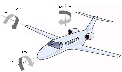
Where v_pitch is the angular velocity in the pitch(X)axis, v_roll is the angular velocity in the roll(y) axis and v_yaw is the angular velocity in the yaw(z) axis. The pitch, roll and yaw of an object in three dimensional space can be illustrated using the figure given below.
If we know the time elapsed between the two consecutive measuring cycles in one axis we can find the angular displacement in that axis simply by multiplying the angular velocity (in °/sec) by the time elapsed (in sec). So the angular displacement in the three axes can be determined using the following equations.
a_pitch=v_pitch *0.047
a_roll=v_roll * 0.047
a_yaw=v_yaw*0.047
Where a_pitch is the angular displacement in x axis, a_roll is the angular displacement in y axis, a_yaw is the angular displacement in Z axis and 0.048 is the time interval. The current orientation of the object in three dimensional space can be determined by the cumulative addition of the angular displacements on each axes. It can be demonstrated by the following equations.
pitch= pitch + a_pitch
roll= roll + a_roll
yaw= yaw + a_yaw
Circuit diagram.
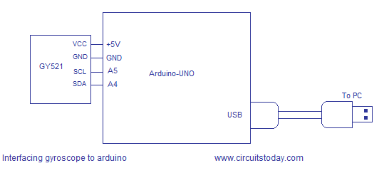
The circuit diagram for interfacing gyroscope to arduino is shown above. +5V and GND connections for the GY521 module are taken from the arduino. SCL and SDA pins of the GY521 are connected to the A5 and A4 pins of the arduino respectively. SCL and SDA pins are used for the I2C communication between the module and arduino.
Program.
#include<Wire.h>
#include<LiquidCrystal.h>
const int MPU=0x68; //I2C address of MPU
int GyX,GyY,GyZ;
float pitch=0;
float roll=0;
float yaw=0;

float v_pitch;
float v_roll;
float v_yaw;
float a_pitch;
float a_roll;
float a_yaw;

void setup()
{

Wire.begin();
Wire.beginTransmission(MPU);
Wire.write(0x6B); //power management register 1
Wire.write(0);
Wire.endTransmission(true);
Serial.begin(9600);
} void loop() { Wire.beginTransmission(MPU); Wire.write(0x43); //starts with MPU register 43(GYRO_XOUT_H) Wire.endTransmission(false); Wire.requestFrom(MPU,6,true); //requests 6 registers GyX=Wire.read()<<8|Wire.read(); GyY=Wire.read()<<8|Wire.read(); GyZ=Wire.read()<<8|Wire.read(); v_pitch=(GyX/131); if(v_pitch==-1) //error filtering {v_pitch=0;} v_roll=(GyY/131); if(v_roll==1) //error filtering {v_roll=0;} v_yaw=GyZ/131; a_pitch=(v_pitch*0.046); a_roll=(v_roll*0.046); a_yaw=(v_yaw*0.045); pitch= pitch + a_pitch; roll= roll + a_roll; yaw= yaw + a_yaw; Serial.print(" | pitch = "); Serial.print(pitch); Serial.print(" | roll = "); Serial.print(roll); Serial.print(" | yaw = "); Serial.println(yaw); }
Notes.
- Power supply for the GY521 module is tapped from the arduino itself.
- Refer the datasheet of MPU6050 for more idea.
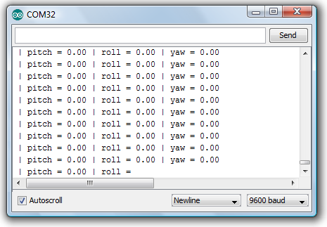
- Screen shot of the serial monitor window during interfacing gyroscope to arduino is shown below.
- The same program can be modified to add an LCD display.I will show it soon.
- Values and equations shown in the program are slightly modified for accuracy.
- There is a temperature sensor also in the MPU6050. The program below shows how to use it.Circuit diagram is the same.
#include<Wire.h>
#include<LiquidCrystal.h>
const int MPU=0x68; //I2C address of MPU
float temp;
void setup()
{
Wire.begin();
Wire.beginTransmission(MPU);
Wire.write(0x6B); //power management register 1
Wire.write(0);
Wire.endTransmission(true);
Serial.begin(9600);
}

void loop()
{
Wire.beginTransmission(MPU);
Wire.write(0x41); //starts with MPU register 41(TEMP_OUT_H)
Wire.endTransmission(false);
Wire.requestFrom(MPU,6,true); //requests 2 registers

temp=Wire.read()<<8|Wire.read();
temp=(temp/340)+36.53; //equation for temperature from datasheet
Serial.print(" Temperature = "); Serial.println(temp);
delay(100);
}
7 Comments
Pls help me there shows an error message with” registers 1″ in pro
#include
#include
const int MPU=0x68; //I2C address of MPU
int GyX,GyY,GyZ;
float pitch=0;
float roll=0;
float yaw=0;
float v_pitch;
float v_roll;
float v_yaw;
float a_pitch;
float a_roll;
float a_yaw;
void setup(){
Wire.begin();
Wire.beginTransmission(MPU);
Wire.write(0x6B); //power management register 1
Wire.write(0);
Wire.endTransmission(true);
Serial.begin(9600);
}
void loop() {
Wire.beginTransmission(MPU);
Wire.write(0x43);
Wire.endTransmission(false);
Wire.requestFrom(MPU,6,true);
GyX=Wire.read()<<8|Wire.read();
GyY=Wire.read()<<8|Wire.read();
GyZ=Wire.read()<<8|Wire.read();
v_pitch=(GyX/131);
if(v_pitch==-1) {v_pitch=0;}
v_roll=(GyY/131);
if(v_roll==1) {v_roll=0;}
v_yaw=GyZ/131;
a_pitch=(v_pitch*0.046);
a_roll=(v_roll*0.046);
a_yaw=(v_yaw*0.045);
pitch= pitch + a_pitch; roll= roll + a_roll;
yaw= yaw + a_yaw;
Serial.print(" | pitch = ");
Serial.print(pitch);
Serial.print(" | roll = ");
Serial.print(roll);
Serial.print(" | yaw = ");
Serial.println(yaw); }
hai,
v_pitch=GyX/131 in this what is 131?