When we learn a new programming language in computer science (say C, PHP or Java), we begin the learning curve with the classic “Hello World” program. We learn some essential keywords used in the programming language, then we learn the structure of the language and finally we begin to play with the language by making it display the two words “hello world” in our computer screen. So that’s how we begin to learn a programming language used to build computer applications. Our world of embedded systems is a little different. We create software to control hardware. In our world, we begin our learning curve by saying “hello world” using an LED. Our way of “hello world” is blinking an LED using the micro controller under study.
In this article, we are going to blink an LED using our arduino board. I will be using an Arduino Uno board to demonstrate the whole process. Before going deep, if you are very new to arduino, I suggest you read the following articles.
1. What is Arduino – for Beginners – is a great article to begin with. It explains arduino to a naive person. You will learn the basics needed from this article.
2. The Arduino Hardware and Software – explains the different arduino boards, different micro controllers used in them, tells in detail about the software IDE and a little bit about programming language as well.
3. The History and Story behind Arduino– If you are interested in knowing about the history behind development of Arduino board.
Now lets begin playing with our LED adventure. You need an arduino board, an LED, a resistor and a breadboard. Once you have these components in hand, you need to install the Arduino IDE (Integrated Development Environment) on your computer. In addition, you need to setup and configure your Arduino board in your computer (by installing the device driver).
Blink LED with Arduino
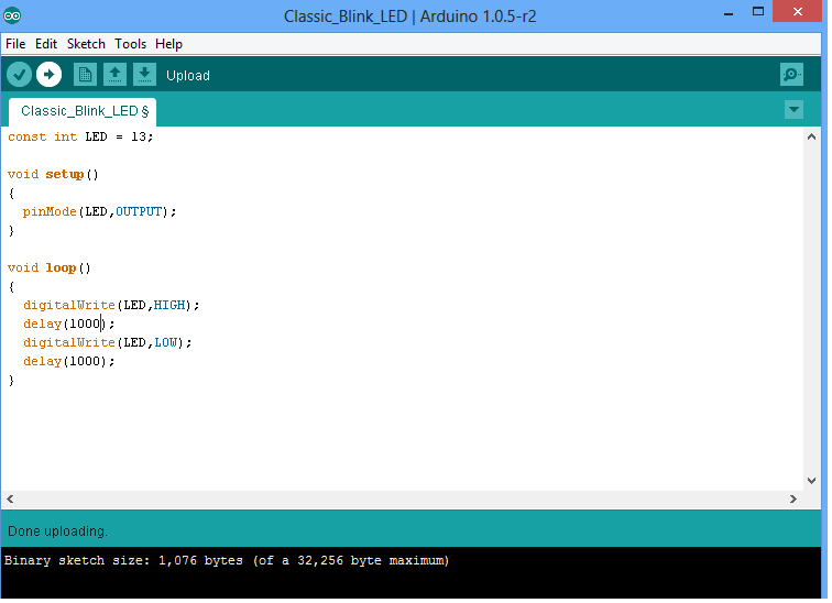
Open the arduino IDE and write the following program to blink an LED. I have written the classic LED blinking example provided in the book Getting Started with Arduino. You may see the screenshot below. After writing the program you may save it with a file name of your choice (find File–>Save on menu bar of IDE)
Now we have to load the program from the PC to our arduino board. To do this perfectly, you have to ensure the following steps.
STEP 1 – Selecting the board
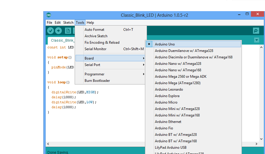
You have to select the arduino board type in your IDE. I am using an Arduino Uno board. To choose the board, find Tools on menu bar. Choose the option “Board” – and select your correct arduino board. I have chosen arduino uno. See the screenshot.
STEP 2 – Select the right port
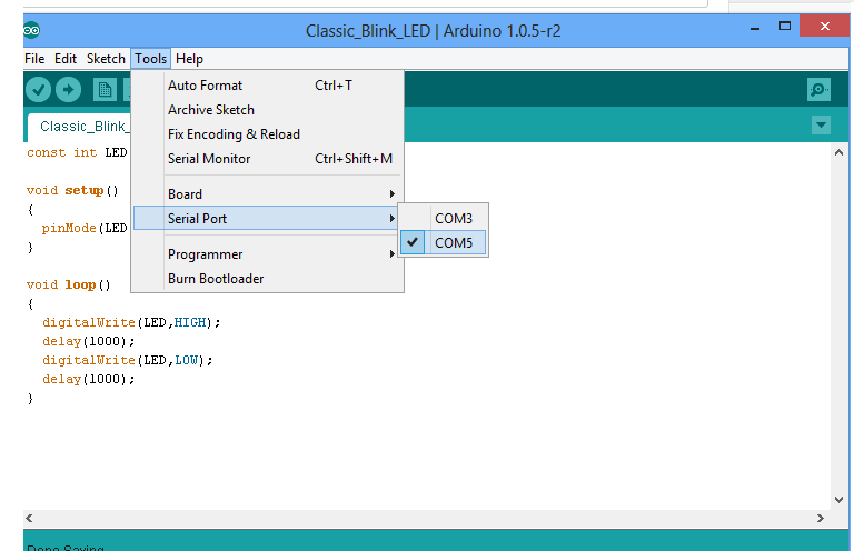
The port number is assigned while installing the hardware driver of board. You may refer the tutorial on Installing Arduino on Windows to know how to find the port number of board. You can find the port number by accessing device manager on Windows. See the section Port (COM & LPT) and look for an open port named “Arduino Uno (COMxx)“. If you are using a different board, you will find a name accordingly. What matters is the xx in COMxx part. In my case, its COM5. So my port number is 5. To select the right port, go to Tools–> Serial Port and select the port number. Refer screenshot below.
Now everything is ready. Your arduino board is ready to communicate with your PC and vice versa. Instructions will be send to arduino board from your PC. Now lets see how to do that.
There are two steps involved in loading the program from your PC to arduino board via the arduino IDE. First step is compiling and second step is called burning. Let’s see in detail.
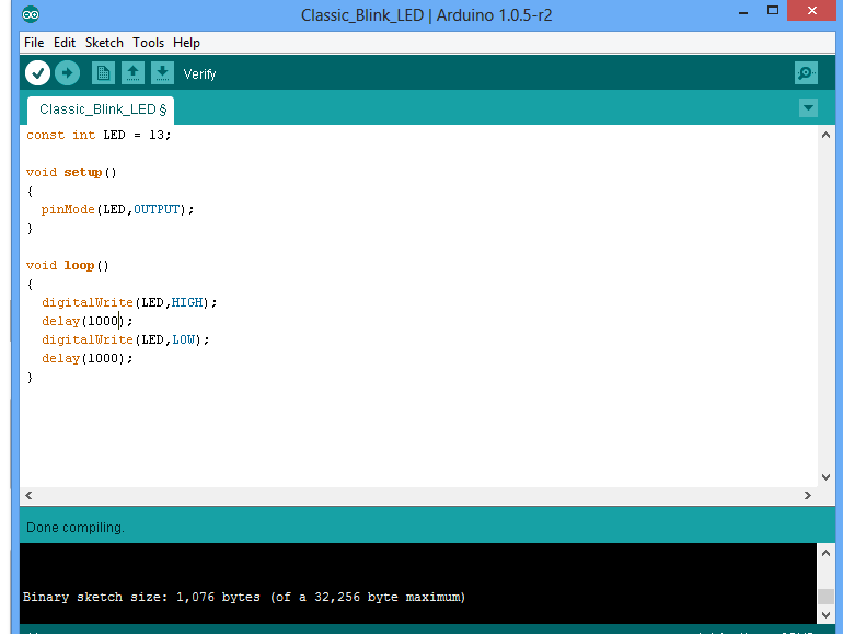
STEP 1:- Compiling – This is the process of converting the code you have just written in arduino IDE to another form which is only understood by the micro controller in your arduino board. In our example, we use arduino uno board. It is made using Avr micro controller (Atmega328). In the arduino IDE, compiling is called as “verify“. So hit the verify button in your IDE (see the button with tick mark just below menu bar). Refer the screenshot given below as well. When you hit the verify button, the program you have written in arduino IDE will be compiled for any errors and then converted to another form that Avr Atmega328 understands. You may refer our article on the Arduino Software and Hardware to know in detail about the language used in arduino.
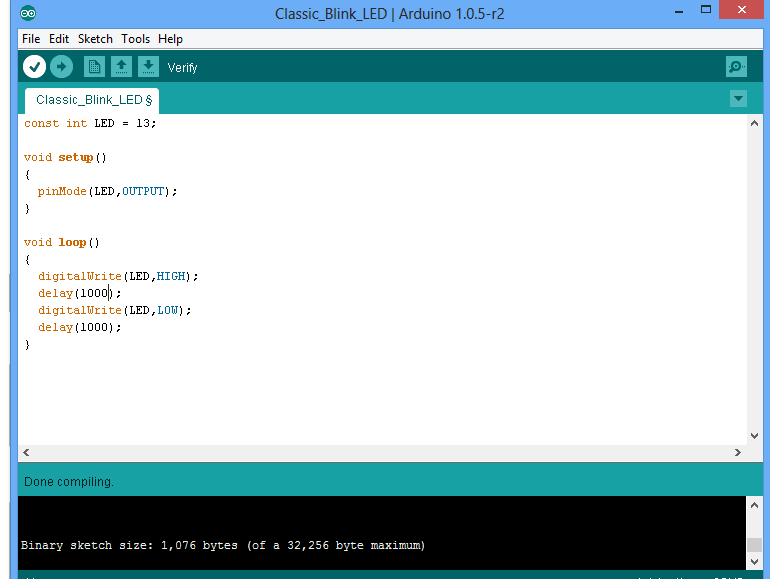
STEP 2:- Burning – Embedded designers use the word “burning” to refer to uploading a program to any micro controller. So in this step, we are going to upload the verified program in arduino IDE to the arduino board. To do this, press the “upload” button (see the button with right arrow mark). A click on the “upload” button will begin the process of burning the compiled program to Avr micro controller on your arduino board. Depending on the size of your program, this will take a little time. If you look on your arduino board, you can see the 2 LED’s near Tx and Rx blinking. This is an indication of successful communication between your PC and arduino board. If the program has been uploaded successfully, you will see a message like “Done Uploading“. If the uploading process was not successful, you will see an error message accordingly. Refer the screenshot given below.
Note:- While I was uploading the “classic LED blink” program to my arduino board, I got an error message on first attempt. It was like “Port COM5 is already in use by another device”. I got it fixed by plugging the board to another USB port in my laptop.
Lets Skim through the Program
Here I am writing the “classic LED blink” program again.
const int LED = 13;

void setup()
{
  pinMode(LED,OUTPUT);
}

void loop()
{
  digitalWrite(LED,HIGH);
  delay(1000);
  digitalWrite(LED,LOW);
  delay(1000);
}
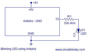
The arduino uno board comes with a pre installed LED at port number 13. This is a small SMD LED marked L and you can find it near port 13. To test the LED blink program, you don’t need to connect a separate LED. However if you wish so, here is a simple circuit to connect an external LED at port 13. A 330 ohms resistor is used to limit current in the circuit. The source supply of +5 volts can be obtained from the USB port of your computer. Your arduino board will be powered up with +5 volts supply from the PC’s USB port, when you connect board via cable. This supply is enough to do simple projects using arduino. Connect anode of LED to port 13 and cathode of LED to ground pin (you can see GND pin just above port 13) as shown in circuit diagram, with the resistor in between port 13 and anode of LED.
The first line of the program const int LED = 13; is called an assignment declaration. Here we declare a new variable with name LED as a constant integer and at the same time we assign the variable to port number 13. From now on, you can replace port 13 with the variable name LED anywhere in the program.
The second line begins with void setup() and it has a block of statements written inside parentheses. Here setup() is a function in APL (arduino programming language) used to declare configuration statements for the micro controller ports. While playing with a micro controller, we need to configure different micro controller ports as INPUT source or OUTPUT. Just as the words say, an INPUT means we are receiving some data into micro controller and an OUTPUT means we are sending some data out of micro controller. In this project we are going to blink an LED at port number 13 of micro controller. To blink an LED means, we have to turn it ON and OFF alternatively at a certain interval. So we are going to send commands to turn LED ON and OFF to port 13 of micro controller (arduino board). To do so, we have to configure port 13 as OUTPUT in our program. This is achieved inside the void setup() block. In arduino programming language, we use a library function named pinMode() to configure micro controller pins of arduino. To configure pin 13 as OUTPUT, we need to write the instruction pinMode(LED,OUTPUT); we used variable LED to represent port 13 as we have already assigned port 13 to variable LED.
Note:- The setup() function is called when a program starts. Use it to initialize variables, pin modes, start using libraries, etc. The setup function will only run once, after each powerup or reset of the Arduino board.
The next block begins with void loop() – here loop() is another predefined function in arduino programming language (APL) . This function executes all statements written inside its parentheses line by line consecutively; from first line inside parentheses to last line. Once the execution finishes last line, it will repeat the process of execution again beginning from first line in parentheses. In other words, loop() is a function that indefinitely executes statements written inside its parentheses. This function enables the micro controller (or arduino board) to do a set of actions as long as it is ON. In our case, those actions are turn LED ON and OFF at certain time intervals. So here is how we are going to tell arduino board to do the ON and OFF process.
APL has an instruction named digitalWrite() – which is an instruction to write some data to a particular micro controller port in arduino board. We have connected LED to pin 13. To turn it ON, we have to supply a voltage at pin 13. We are going to do that via software commands. Since our arduino board is connected to PC via USB, a +5 volts readily available. We need to pass this voltage to port 13 of arduino board. To do so, APL has a keyword instruction called HIGH. So we just need to write an instruction digitalWrite(LED,HIGH); and this instruction when executed by micro controller will supply a +5 volts at port 13. This voltage will power LED and it will turn ON. We have completed 1/3rd of our task now. Now we need to turn LED OFF. How to do that ? You just need to disconnect the voltage supply given at port 13. In APL, there is a keyword instruction named LOW for this purpose. Write an instruction digitalWrite(LED,LOW); and we cut off supply at port 13. This instruction will turn LED OFF. We have completed 2 major tasks by now. What remains is setting a time interval in between ON and OFF time. Let’s prefer a 1 second time delay between ON and OFF time. APL has a function called delay() to do this task of setting time delay. All you need to do is write your desired delay in milli seconds as an argument in the delay function. To get a 1 second delay, we should write delay(1000); and this will impart a delay of 1000 milli seconds in between LED ON and OFF time.
So here is the summary of program inside loop(). digitalWrite(LED,HIGH); will turn the LED ON. Now we need to keep the LED ON for 1 second. We do so by keeping the micro controller idle (or we make it to wait ) for 1 second. delay(1000); is the function we use to keep the micro controller idle for 1 second (even though I wrote idle, the micro controller is actually in execution mode. It is counting an inside timer and continuously checking if it reached 1 second. You will learn about those in next chapters). After 1 second, we need to turn LED OFF. We do so with instruction digitalWrite(LED,LOW); this will turn LED OFF. Now we need to keep the LED in its OFF state for 1 second (before it is turned ON again). To do so we write a delay(1000); instruction once again just below the instruction to turn LED OFF. Since this is the last statement inside loop() function of our program; the micro controller will begin executing from beginning statement inside loop() after waiting 1 second to keep LED OFF. So the LED is ON again after 1 second.
I hope you understood how to say “hello world” using arduino. This is a good start for any one new to electronics and arduino. If you have any doubts, feel free to ask. I have added a photograph of the circuit I tested below. You can also watch the video of LED blinking using arduino.
Photograph of blinking LED using Arduino
![Blink_Led_with_Arduino [Photograph] Photograph of blinking LED with Arduino](jpg/blink_led_with_arduino.jpg)

Comments are closed.