Build a Real Time Clock using Arduino and DS1307 RTC Module
In this article, we are going to build an Arduino Real Time Clock using DS1307 RTC Module and 16×2 LCD module for display. First of all, let’s see how to interface RTC Module to Arduino. There are different kinds of RTC modules available in the market. We are using the most common RTC module comes named DS1307 IC, an LCD module and Arduino Uno for this tutorial. Interfacing an RTC module to Arduino is pretty simple. You only need to make 2 connections between the RTC module and Arduino. So let’s get to business!
A Real Time Clock module is basically a time tracking device which gives the current time and date. RTC module that comes with DS3231 IC have the provision to set alarms.
Notes On DS1307 RTC Module
Here we are using an RTC module with clock chip DS1307 based on I2C protocol (Two Wire Protocol). The module provides details such us second, minute, hour, day of week, day of month, month and year including correction for leap year. It can operate either in 12 Hour or in 24 Hour format. Current consumption of this module is nano ampere range . Even a 3V battery can power it for 10 years maintaining an accurate clock and without any external power. DS1307 has a memory area of 64 bytes of which the first 8 bytes are reserved as RTC register area and the remaining 56 bytes are allotted as general purpose RAM. The details about current date and time is stored in its register area as Binary Coded Decimals. The module communicates with the microcontroller using a serial communication protocol called I2C. The I2C bus physically consists of 2 active wires. The wires, called SDA and SCL, are both bi-directional. SDA is the Serial Data line, and SCL is the Serial CLock line. Every device connected to the bus has its own unique device address, no matter whether it is an MCU or RTC module. Each of these chips can act as a receiver or transmitter, depending on the functionality.
DS1307 will act as slave in the communication network and controller can only access the slave by initiating a start condition along with a device address. There after we need to send the register number in order to access the value inside. The interface to the Arduino is simple I2C with SDA and SCL pins are connected to the corresponding I2C pins of arduino. At the software side we are using an arduino library named “Wire” for I2C communication. This library allows you to communicate with I2C / TWI devices.
I hope you understood so far! Let’s get to the circuit diagram! So given below is the circuit diagram to connect RTC module to Arduino.
Circuit Diagram – Arduino Real Time Clock
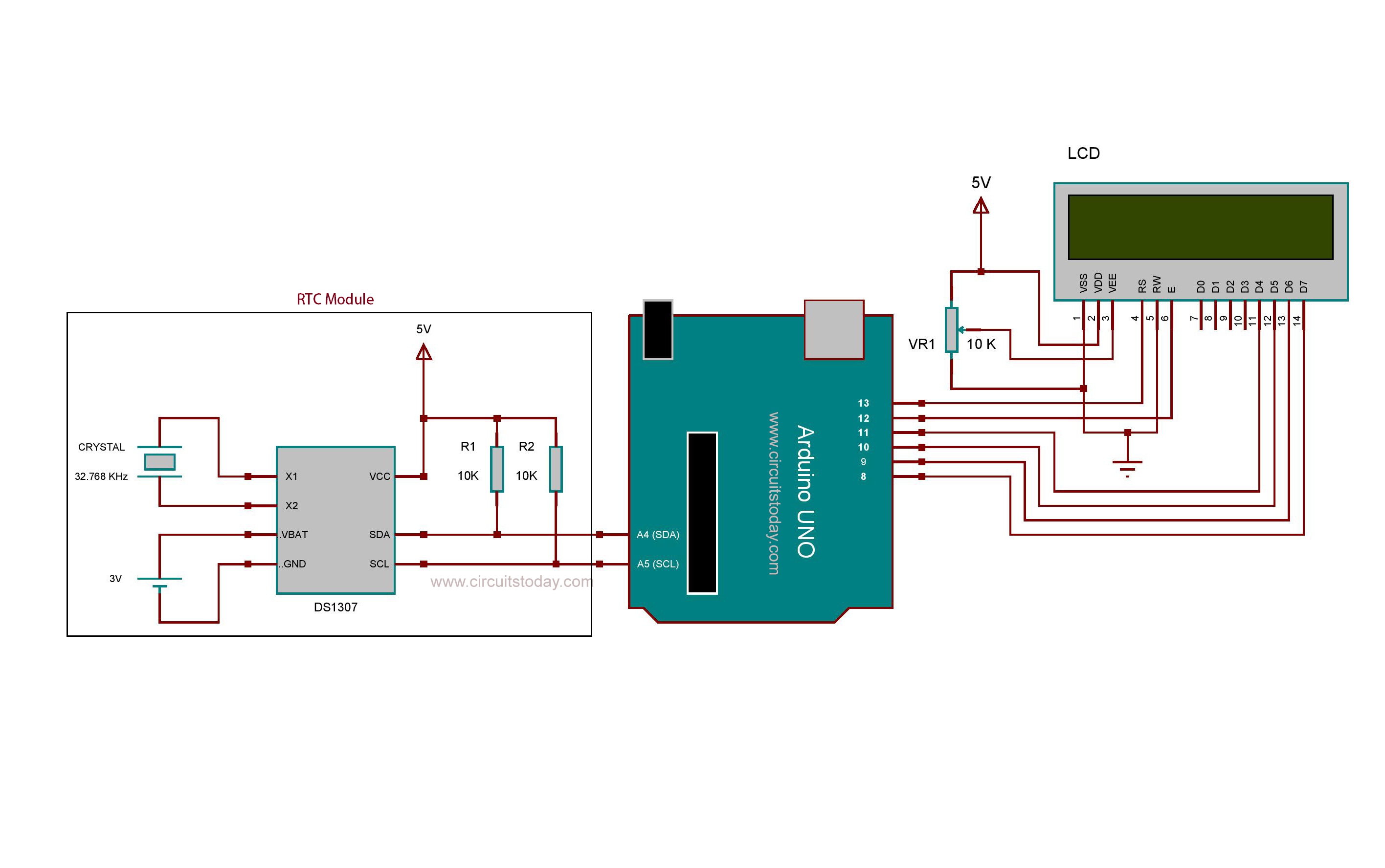
Make the connections as shown! Now lets get to the coding part.
The Program/Code Explanation
We begin including LiquidCrystal library into the program. In the next line, we create a constructor of Liduidcrysal with name lcd and we pass the digital pin numbers as parameters. The actual format is like SoftwareSerial lcd (RS,EN,D4,D5,D6,D7); You will get more details about LCD interfacing on article “Interfacing LCD to Arduino”.
Here we are focusing mainly on RTC module interfacing. As mentioned earlier a library named “Wire” is used here for I2C communication. The Wire.begin() function will initiate the wire library. Since it is used for initializing the library, it need to be called only at the beginning. Wire.beginTransmission() is the function used for sending device address. Then with Wire.write()we will send the number of the register whose value we need to access.
The Wire.endTransmission() function will end the transmission. Wire.requestFrom() function is used by the master to request bytes from the module. Wire.read() will reads a byte that was transmitted from slave device to Arduino after a call to requestFrom().
In DS1307, bytes are stored as binary coded decimals. So before writing values into the registers, we need to convert it into BCD(Binary Coded Decimals). Like wise, after reading values from the register area, it should be converted into decimal. Dec_To_BCD() and BCD_To_Dec() are the functions used for this.
Before reading values from the RTC module, we must set the time and date at once. The function used for this is the setTime() function. We should pass the actual time details as parameters. The actual format is like setTime(sec,min,hour,dow,dom,month,year); .
Here we are using DS1307 in 24 hour mode. And then convert it into 12 hour mode at the software side. So the time details should be in 24 hour mode while passing arguments to setTime() function. After uploading the program at once, you should reupload the code by commenting the setTime() function. Otherwise the setTime() function will corrupt the current time while every time you reset the Arduino.
getTime(), getDate(), getWeek() are the functions used for accessing the seven data registers in DS1307. getTime() function will provides the hour minute and second details. getDate() gives the day, month and year. And getWeek() will return the day of week. These provides data as decimals. So we should convert it to time format and as usable string. getTimeStr() is the function which will return the current time as a single string. Like wise, getDateStr() will return the current date and getWeekStr() will return the day of week as string.
You can display the current time on an LCD by simply calling the getTimeStr() function inside the lcd.print(). For example , lcd.print( getTimeStr() ); .
Mode12() and Mode24() are the functions for switching the mode of displaying time. If you want to display the current time in 12 hour mode, you should call the Mode12() function before using getTimeStr(). If you have any doubts please ask in comments.
Comments are closed.