In this article, we are going to read the colors using the TCS230 color sensor (RGB Sensor) and Arduino Uno. The TCS 230 color sensor senses the color light by using the photodiodes. The sensor converts the readings from the photodiode into a square wave by using the light to frequency converter. The frequency of these waves is directly proportional to the light intensity. Then the Arduino reads these square waves and gives us the values of the RGB colors. So let’s begin our tutorial on Interfacing Arduino and RGB Color Sensor TCS230.
Pin out – TCS230 (RGB Color Sensor)
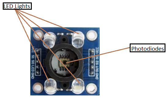
If you take a closer look at the sensor, you will see that it contains an array of photodiodes which are used to sense the color light. The sensor also consists of four LED lights.
The sensor has 10 pins; S0, S1 are for setting the frequency and S2, S3 are for reading the color values. The out pin is supposed to give the output to Arduino in the form of a square wave. The other pins are for powering the sensor.
Working of RGB Color Sensor
TCS230 color sensor consists of an 8X8 array of photodiodes. These photodiodes consist of three different color filters. 16 of them are red, 16 of them are green, 16 of them are blue and 16 of them are clear (No color). Every 16 photodiodes are connected in parallel. So, if we want to read colors, then we can read them by using the S2 and S3 pins. The pin combination for reading the RGB colors is as follows
| S2 | S3 | Color |
| LOW | LOW | Red |
| LOW | HIGH | Blue |
| HIGH | LOW | Clear |
| HIGH | HIGH | Green |
So with the help of pin combinations provided in the above table, we can read values of each color. First of all, we have to read the Red color by making both the S2 and S3 pin low. Then, we read the Green color by making both the pins high and finally, we read the Blue color by making the S2 pin low and S3 pin high. After that, we will map these values to 0-255 and show the color values on the serial monitor.
The sensor also has two more pins which are S0 and S1. These pins are used to set the frequency to 0%, 2%, 20% or 100%. The pin combination for setting the frequency using these pins is as follows
| S0 | S1 | Output Frequency |
| LOW | LOW | 0% |
| LOW | HIGH | 2% |
| HIGH | LOW | 20% |
| HIGH | HIGH | 100% |
In our code, the frequency is set at 20%. You can set the frequency to any other value (you desire), but the output values will change according to the set frequency and you will have to map the color values relative to the set frequency.
Circuit Diagram and Explanation
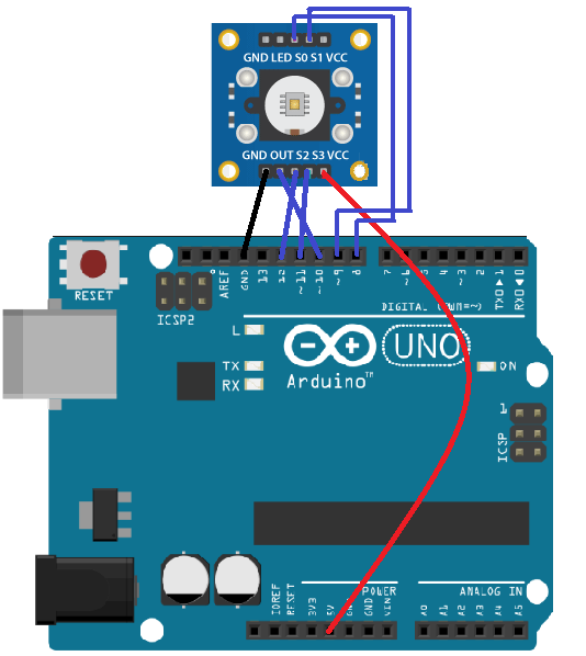
The connections of Arduino with the color sensor TCS230 is as given below:
| TCS230 | Arduino Uno |
| VCC | 5V |
| GND | GND |
| S0 | Pin 8 |
| S1 | Pin 9 |
| S2 | Pin 12 |
| S3 | Pin 11 |
| OUT | Pin 10 |
Code/Program – Arduino Color Sensor Interfacing
int s0_pin =8;

int s1_pin =9;

int s2_pin =12;

int s3_pin =11;

int out_pin =10;


void setup() {

Serial.begin(9600);

pinMode(s0_pin, OUTPUT);

pinMode(s1_pin, OUTPUT);

pinMode(s2_pin, OUTPUT);

pinMode(s3_pin, OUTPUT);

pinMode(out_pin, INPUT);

digitalWrite(s0_pin,HIGH);

digitalWrite(s1_pin,LOW);

}


void loop() {

digitalWrite(s2_pin,LOW);

digitalWrite(s3_pin,LOW);

int red_color = pulseIn(out_pin, LOW);

red_color = map(red_color, 25,72,255,0);

delay(50);

digitalWrite(s2_pin,HIGH);

digitalWrite(s3_pin,HIGH);

int green_color = pulseIn(out_pin, LOW);

green_color = map(green_color, 30,90,255,0);

delay(50);

digitalWrite(s2_pin,LOW);

digitalWrite(s3_pin,HIGH);

int blue_color = pulseIn(out_pin, LOW);

blue_color = map(blue_color, 25,70,255,0);

delay(50);

Serial.print("RED: ");

Serial.print(red_color);

Serial.print("  ");

Serial.print("GREEN: ");

Serial.print(green_color);

Serial.print("  ");

Serial.print("BLUE: ");

Serial.print(blue_color);

Serial.println("  ");

delay(1000);

}
Code Explanation
First of all, we have to initialize the pins of the color sensor that we are going to use in the project. The s0, s1 pins are to set the frequency to 2%, 20% or 100% and the s2, s3 pins are to get the values for the red, green and blue color. The out_pin will give us the output values of the color sensor.
int s0_pin =8;

int s1_pin =9;

int s2_pin =12;

int s3_pin =11;

int out_pin =10;
In the setup function, we have declared s0, s1, s2 and s3 pins as output pins because Arduino writes commands to the color sensor through these pins. The out_pin is declared as input because the Arduino reads the output from the color sensor through this pin.
pinMode(s0_pin, OUTPUT);

pinMode(s1_pin, OUTPUT);

pinMode(s2_pin, OUTPUT);

pinMode(s3_pin, OUTPUT);

pinMode(out_pin, INPUT);
The following commands will set the frequency to 20%. You can also set the frequency to 2% or 100%. If you set the frequency to 2% or 100%, then the output values will be changed according to that and you have to map these values accordingly to get the RGB values.
digitalWrite(s0_pin,HIGH);

digitalWrite(s1_pin,LOW);
First of all in the loop function, we set the s2 and s3 pin low to get the red color values. The output of the sensor for s2 and s3 pin low will be from 25 to 72. So, we will map these to 255-0 to get the red color value.
digitalWrite(s2_pin,LOW);

digitalWrite(s3_pin,LOW);

int red_color = pulseIn(out_pin, LOW);

red_color = map(red_color, 25,72,255,0);

delay(50);
Then we set the s2, s3 pins high to get the value for the green color. The output for s2, s3 pin high will be from 30 to 90 and we will map these values from 0 to 255 to get the green color value.
digitalWrite(s2_pin,HIGH);

digitalWrite(s3_pin,HIGH);

int green_color = pulseIn(out_pin, LOW);

green_color = map(green_color, 30,90,255,0);

delay(50);
Similarly, by doing the s2 pin low and s3 pin high, we will get the blue color value.
digitalWrite(s2_pin,LOW);

digitalWrite(s3_pin,HIGH);

int blue_color = pulseIn(out_pin, LOW);

blue_color = map(blue_color, 25,70,255,0);

delay(50);
In the end, we print the values for the red, green and blue color on the serial monitor.
Serial.print("RED: ");

Serial.print(red_color);

Serial.print("  ");

Serial.print("GREEN: ");

Serial.print(green_color);

Serial.print("  ");

Serial.print("BLUE: ");

Serial.print(blue_color);

Serial.println("  ");

delay(1000);
So that’s it! We have finished our tutorial on Interfacing Arduino and Color Sensor. If you have any doubts, please ask in comments.
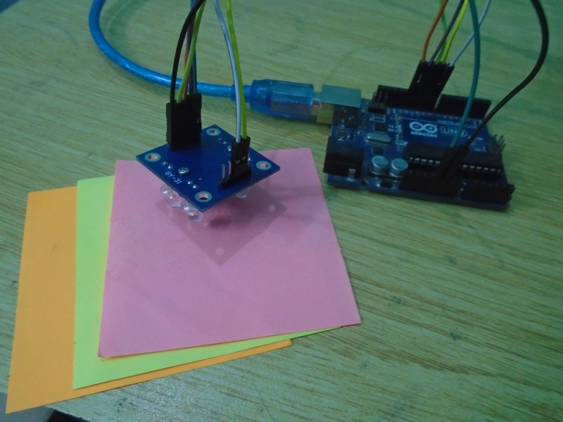
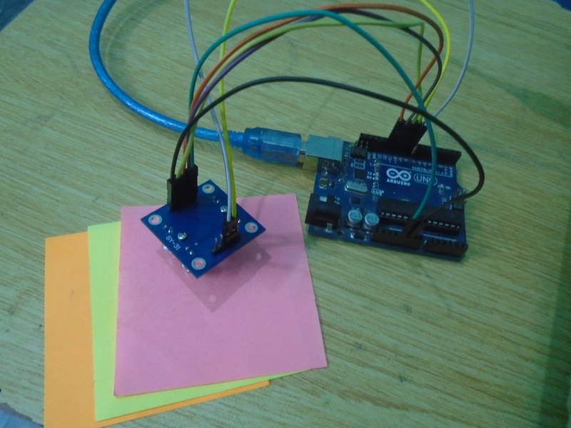
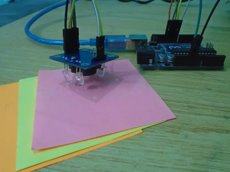
Photographs
2 Comments
Hi..when I placed a white paper in front of color sensor..the values of rgb are changing continuously..and when I changed the color also..it is producing different values..how can I know what color is exactly it is detecting
Mapping the color ranges is to chart the sensor characteristics right?
In case we have already found these values and we want to use the sensor in some other project, shall we directly use the values or should we map it again in that project code too?