Square wave generator using uA741 opamp.
uA 741 opamp IC.
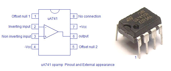
uA 741 is a very popular monolithic opamp IC that can be used for a lot of applications. The uA741 opamp was first introduced by Signetics and now a lot of manufacturers produce them. uA741 is commonly available in an 8 pin DIP plastic package and contains a single opamp. They typical applications of uA741 are differentiator, integrator, adder, subtractor, differential amplifier, instrumentation amplifier, small signal audio amplifier, frequency generator etc. Even though uA741 is generally operated from a split power supply it can be compromised to operate on a single supply. The pin configuration of uA741 opamp is shown in the figure below.
The supply voltage range of uA741 is from +/- 5V to +/- 18V. Pin number 1 and 5 are meant for offset error adjustment. This can be done by connecting a 10K pot with its end attached to pins 1,2 and the viper to pin 4. The maximum power uA741 can dissipate is 500mW. Additional driver circuits are required for any application that requires more than the above stated power rating.
Square wave generator using uA741.
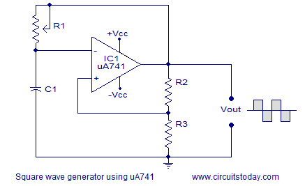
Square waves belonging to a wide range of frequencies and duty cycle can be generated using the uA741 opamp. The circuit diagram of a typical square wave oscillator using uA741 is shown in the figure below.
In the circuit diagram capacitor C1 and potentiometer R1 forms the timing part. Resistors R2 and R3 forms a voltage divider network which supplies a fixed fraction of the output voltage into the non-inverting pin of the opamp as a reference voltage.
Working of the square wave generator using uA741
Initially the voltage across the capacitor C1 will be zero and the output of the opamp will be high. As a result the capacitor C1 starts charging to positive voltage through potentiometer R1. When the C1 is charged to a level so that the voltage at the inverting terminal of the opamp is above the voltage at the non-inverting terminal, the output of the opamp swings to negative. The capacitor quickly discharges through R1 and then starts charging to negative voltage. When the C1 is charged to a negative voltage so that the voltage at the inverting input more negative than that of the non-inverting pin, the output of the opamp swings back to positive voltage. Now the capacitor quickly discharges the negative voltage through R1 and starts charging to positive voltage. This cycle is repeated endlessly and the result will a continuous square wave swinging between +Vcc and -Vcc at the output.
The time period of the output of the uA741 square wave generator can be expressed using the following equation:
The common practice is to make the R3 equal to R2. Then the equation for the time period can be simplified as:
T=2.1976R1C1
The frequency can be determined by the equation: F=1/T
Testing the square wave generator using uA741.
Added soon.


8 Comments
easy to understand. thank u
Very good information and its easy to implement..
please i have build the circuit above with r3=100k and r4=10k r2=47k r1=2.5M c=0.1 Mf but it doesnt give me square wave it has gave me dc output pleeeeeeease help me
yes it’s clearly to understand but how to calculate Its Frequency
ya .its really good still the waveforms can be shoewn
nice to understand