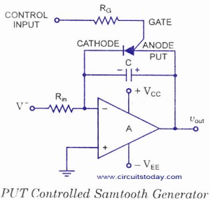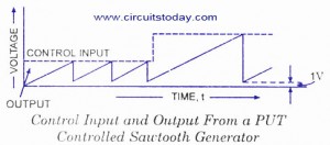
A PUT controlled sawtooth generator circuit is shown in figure. When power is first applied, the programmable unijunction transistor (PUT) is off. The capacitor C begins to charge up and the output voltage rises. This continues until the output voltage (which is also the PUT anode voltage) is about 0.7 V above the control input (the gate voltage). The PUT gets switched on. The capacitor C is shorted out through PUT and, therefore, capacitor gets immediately discharged through the PUT. The output voltage, which is equal to the voltage across the capacitor, falls. When the current through the PUT falls below its holding current IH, it goes off and the cycle repeats. When the PUT turns off, approximately 1 V is usually left on the capacitor. The output waveform is shown in figure.

The time period of the PUT controlled sawtooth generator depends on the charge rate (V/RC) and the control voltage Vcontrol. This is obvious from figure.
Time period, T = Distance / Rate = (Vcontrol + 0.7 V) – 1V / (І-V І/RC)
= Vcontrol RC / І-V І………………. {І-V І = magnitude of –V}
and frequency, f = 1/T = І-V І/Vcontrol RC
The PUT controlled sawtooth generator can be used as a voltage-to-frequency converter.
Precautions
- The cathode of the PUT must be tied to ground or virtual ground and current flows only from anode to cathode. So PUT cannot be used to control a negative ramp generator.
- To turn-off the current through the PUT must drop below its holding current IH (specified by the manufacturer). When the PUT is on, a current equal to that used to charge the capacitor, in addition to capacitor discharge current, flows through the PUT. This current flows through R to V– must be below IH.
That is, I = V/R < IH
Failing which, once the PUT goes on, it will be held on by this charge current, even when the capacitor has fully discharged. This charge current can be lowered by increasing R or reducing negative voltage V-.. However, both of these factors affect the change rate and. Therefore, the frequency. For keeping frequency unaffected the changes in either R or V– will have to be balanced with appropriate changes in C.

Comments are closed.