Radio Collar Transmitter
Radio collars or tracking collars are tracking devices used to study animal migration patterns, they are also used to keep tab of endangered species. In India, radio collars are commonly used on tigers to keep track of them. Obviously, a radio collar has a strap which is worn around the neck of the animal and a radio transmitter. Our project here is to make such a radio transmitter device which can be used for tracking. We are using NE555 IC to simplify the circuit.
Description
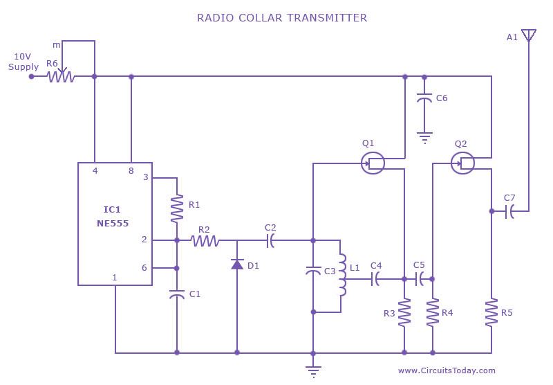
This is the circuit diagram of a radio transmitter suitable for fitting on radio collars. The circuit transmits a pulse in the FM between band 88MHz to 105Mhz, which can be adjusted. The IC Ne 555 is wired as an astable multivibrator for producing the tone. L1, C3 and Q1 form the modulator. Q2 performs the final power amplification.
Notes
For the inductor make 5 turns of .5 mm dia insulated copper wire on a standard ball pen refill. Remove the refill and make a tap at the centre of the coil. To vary the transmission frequency try experimenting with a number of turns. Careful! whatever may be the no of turns the tap must be at centre. Use a 50 cm long insulated copper wire as an antenna.
Parts List
R1…………………………………. 10K
R2 …………………………………1 M Ohm
R3 ………………………………….330 Ohm
R4 …………………………………..1 M Ohm
R5……………………………………. 330 Ohm
R6 ……………………………………200 Ohm POT
C1 ……………………………………..0.1 uF Ceramic
C2…………………………………….. 0.01 uF Ceramic
C3…………………………………….. 13 pF Ceramic
C4 ,C5, C6,C5 ……………………..0.01 uF Ceramic
Q1 ,Q2 ………………………………..2N4392 JFET
D1 ……………………………………….1N 914 Diode
IC 1……………………………………… NE 555
Circuit Diagram.


Comments are closed.