Description.
A variety of humidity tester circuits are available, but this is a circuit which is as simple as possible. Using only a transistor, LED and few resistors, this circuit can be used to check the humidity level of materials like soil, paper etc.
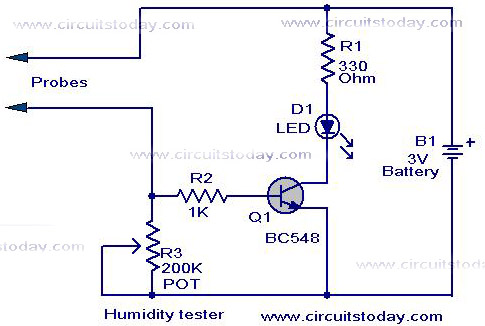
When the humidity in a substance increases the current conducted through it also increases. This is the working principle. If there is required humidity, the current through R3 will be sufficient to produce a voltage drop across R3 which is sufficient enough (0.7V) to switch on the transistor and LED glows. R1 is the current limiting resistor for LED. R1 protects the transistor from accidental shorting of the probes.
Circuit diagram with Parts list.
Notes.
- The sensor probes can be anything like iron nail,pin paper clip etc.
- To calibrate the circuit for particular density, insert the two probes to the required material and adjust R3 so that the LED glows. The LED will glow whenever the humidity of the testing sample becomes equal to this humidity level.
- A 3V battery can be used to power the circuit.
- Another general purpose NPN transistors like BC107, BC148, 2N2222 etc can be also used for Q1.
6 Comments
i want a abstract on it please
it works 100%
Thanks for schematics. I just built a “plant tester” for my kids based this. Simple and nice solution.
hi
i want to learn about very low cost tester
please send about pdf files and ppt and other files
thanks and regard
mounesh.kambar