ICL 8038 waveform generator.
ICL8038 is a monolithic waveform generator IC that can produce sine, square and triangular waveforms with very little distortion. The frequency can be programmed from 0.001Hz to 300 KHz using external timing capacitor and resistor. Frequency modulation and sweeping can be attained by using an external voltage. Other features of the ICL8038 are high linearity, high level outputs, simultaneous sine, square, triangle wave outputs, low external parts count, high temperature stability etc.
The working of ICL8038 is as follows. The external timing capacitor (C2 in the circuit diagram) is charged and discharged using two internal current sources. The first current source is on all the time and second current is switched ON and OFF using a flip-flop. Suppose the second current source is OFF and the first current source is ON, then the capacitor C2 will be charged with a continuous current (i) and the voltage across C2 increases linearly with time. When the voltage reaches 2/3 supply voltage, controlling flip flop is triggered and the first current source is activated. This current source carries double the current (2i) making the capacitor C2 is discharged with a current i and the voltage across it drops linearly with time. When this voltage reaches 1/3 supply voltage, the flip flop is resetted to the initial condition and the cycle is repeated again.
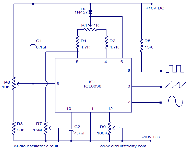
Circuit diagram – ICL8038 audio oscillator.

The circuit diagram given above shows a variable audio frequency oscillator using ICL8038. Such a circuit is very useful while testing audio related projects. The frequency range of this circuit is 20Hz to 20KHz. POT R6 can be used for adjusting the frequency while POT R9 can be used for adjusting the distortion. POT R4 can be used for adjusting the duty cycle while POT R7 can be used for nullifying the variations in duty cycle. C2 is the external timing capacitor and R5 is a pull up resistor.
Notes.
- The circuit can be assembled on a vero board.
- Use +10 /-10V DC dual supply for powering the circuit.
- The power supply must be well regulated and filtered.
- All fixed resistors are rated ¼ W.

16 Comments
Looking at this circuit I see there are are at least 3 problems:
1 I assume the supply is +10v-0v–10v, where then is the 0v connected?
2 what forms the output of the circuit, I see the +ve sides are formed from the outputs of the IC on either pins2,3 & 9 of IC1, what forms the -ve output?
3 I appears that pin 9 of IC1 is connected via a 15K resistor to the +10v line, are there similar connections to pins 2 & 3?
Thanks for sharing you work.
I want to analyze this circuit but i do not have the 8038 spice model.
I searched but could not find any website.
If you have it, could you post?
where this IC ICL8038 is available. can i get it through online purchase.it is not available in electronic component shops.
I am sorry but i think it lacks of ground point or i am wrong?
Either is grnd or negative either one only. If single supply connect 20 volt to pin6 and 0 (gnd) to pin 11. Any instrumentation dealer in bangalore hyderabad bombay or chennai can supply as it is a intersil’s function generator chip..
To terence m. maloney
I think if you look at the specs for the chip, you’ll find it requires a supply of 15 v, NOT +10v as shown, the -10v should be 0v.
Also for C1 I have a value of 100nF, R5 is 10K, C2 though seems to be a paper rather than an electrolytic. Make very sure that your input voltage is VERY stable indeed.
Electrical Specifications VSUPPLY = 10V or +20V, TA = 25oC, RL = 10k, Test Circuit Unless Otherwise Specified
Supply Voltage Operating Range VSUPPLY
V+ Single Supply +10 – +30 +10 – +30 +10 – +30 V
V+, V- Dual Supplies 5 – 15 5 – 15 5 – 15 V
Can this circuit be used to design a sine wave inverter?
Pls sir, can the audio oscillator circuit be futher amplified with mosfet also can 12volt dc be used to power the circuit instead of 10v. Dc.
hope that this will work as it should do to save me the expence of buying a function generator.Where does the 0v of the power supply gets connected?
Hi HB 1volt RMS @ 5mA is the maximum output possible into 200 ohms load.
Hi Mani Use modulation transformer or modulation transistor to do the job.
How am I mix the radio frequency with this Sir? for IFT, Osc.,and Ant coil tunning
how much would be the output voltage and current on the waveform?
thank you