Description.
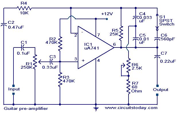
A preamplifier circuit suitable for high impedance type electric guitar pickups is given here.The circuit is based on a uA 741 op-amp (IC1).The IC1 is wired as a non-inverting amplifier.The POT R1 can be used as a volume controller.The POT R6 can be used as tone controller.The switch S1 is used to produce “brilliant” or “soft” tonal effects.
Circuit diagram with Parts list.
Notes.
- Assemble the circuit on a good quality PCB or common board.
- The amplifier can be powered from a 12V battery or 12V DC power supply.
- Up to 24 V DC can be used to power the circuit.i recommend 12 V DC.
- The IC 1 should be mounted on an IC base .
5 Comments
wich caps are electrolitics?
Is there any modifications in this circuit if i will use it in a bass guitar???
thanks for the sharing… it is very good circuit.
Hi,
We have tried the circuit in two stages. This really gives a very good effect. Thank you the sharing.
You folks who know electronics, please advise me! I am wanting to design some buffer circuitry for a homebrew fancy guitar selector gadget. I know that op-amps will give me more flexibility in circuit design over JFETs, but some people have observed that op-amp buffers sound “colder and more sterile”.
Do you have any opinions? Would a JFET circuit really preserve the guitar’s tone better? If there is a difference that could be noticed, I think I’d be willing to do the more involved JFET design, though I’ll need to know how to boost the gain (I’ll want to boost the signal be a few db), which of course op-amps can do more easily.
Also, seems to me a JFET circuit might consume less power than using op-amps — Agree? Disagree?
I know this is a rather ethereal question, but if any of you know about this, please advise.
/Mark