Description.
The circuit given here can be used to control the brightness of low power incandescent lamps. The circuit is based on IC NE555 which is wired as an astable multivibrator with variable duty cycle. The output of IC is connected to the base of transistor Q1.The Q1 drives the lamp. The duty cycle of the multivibrator can be varied by varying the POT R4.As a result, the brightness of the lamp varies according to the position of the POT R4.The same circuit can be also used for speed control of small DC motors.
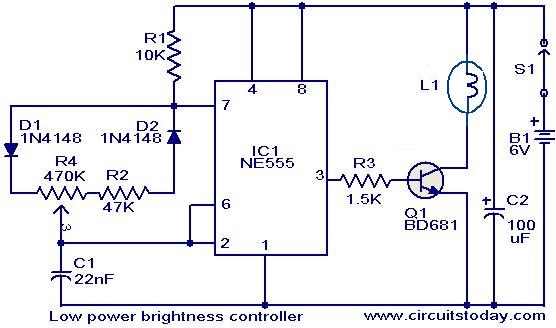
Circuit diagram with Parts list.
Notes.
- The lamp L1 can be a 6V / 200 mA lamp.
- The switch S1 can be SPST ON/OFF switch.
- The IC1 must be mounted on a holder.
- The circuit can be wired on a good quality PCB or common board.
6 Comments
Bd681 is actually is what? cuz i tried searching it on proteus and there is no bd681.
sorry for the broken english ^_^
Hello Dev,
We can use PWM (Pulse width Modulation)for dc lights & SCR for ac light control.
i want thee dancing light project like the stage lights
The LEDs may not respond like filament bulbs for smooth brightness variation. For brightness variation in LEDs the current through them should be varied from 3 to 25mA. Hence a variable constant current source is essential for the LED dimming operation. There are so many circuits available in Circuits today projects itself.
Hi,
Can I use this circuit to Dim LED lights ???
Also How can I remove the POT and put a push button switch that will give different brightness on each push.
Thanks
Dev
you can connect 3 ordinary LEDs or 2 white LEDs in series in place of the lamp. A resistor must be added in series with the LEDs to limit the LED current to about 20mA.
If you need a push button control, you have to connect a digital POT IC like DS1669 in place of R4. I haven’t tried it. But I think its a good idea.