Description.
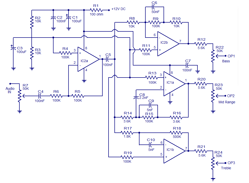
Here is the schematic of a 3 way active cross- over network circuit that finds a lot of application in audio amplifier systems. The heart of this circuit is National Semiconductor’s IC LF353 which is a dual JFET input operational amplifier with internally compensated input offset voltage. The IC LF353 has high bandwidth, low offset currents, and low input bias current due to the JFET based input stage.
The working of the circuit is very simple and straight forward. Two LF353 ICs are used here. The input audio signal is first buffered using the opamp IC2a and POT R7 can be used to adjust the gain of this buffer stage. The buffered audio input is then spited into three bands using the filters built around the opamps IC2b, IC1a and IC1b. IC2b handles the bass range, IC1a handles the mid range and IC1b handles the treble range.POT R22, R23 and R24 can be used to adjust the bass, midrange and treble respectively.
Circuit diagram.
Notes.
- Assembling the circuit on a good quality PCB improves the sound quality.
- The circuit cab be powered from a 12V DC supply.
- he ICs must be mounted on holders.
- The outputs OP1, OP2 and OP3 must be connected to the respective inputs of the multichannel power amplifier stage (not shown in circuit).


11 Comments
is it possible to explain how the circuit works i realy could use it for my thesis, i’m not in a desinger school but a more practical electronics school so we just need a schematic and the explanation.
It would be realy helpfull
already thanks
dont i need a connection from r2/r3 (10k) to c3 (100uF)? (a dot in the schematic so they are connected)?
hello
dont i need a connection (a dot) r2/r3 to c3?
The Circuit’s outputs must be connected to amplifiers inputs or to the speakers?
Can i have the PCB design?
Hi Ravina The corresponding pots of each sound spectrum to be adjusted to suit the speakers(efficiency placement etc)and room acoustics and our ear’s sensitivity for the spectrum.
This design is a basic low pass, band pass and hi pass filters, found in any text book.
arent the gains for the bass,midrange and treble different??shouldnt they be the same??
How did you design the capacitor values for the circuit?
Hi John The total current requirement for the circuit at 12volt is less than 10mA.
what current rating is needed for active electronic cross over?
All your circuits are very interesting. We need more number of circuits on water Level Controller with timer. When the water reaches top level of over head tank the motor ‘off’. Again the on time is after 60 mts or 30mts, or 45 mts.