Power Amplifier Circuit – 25 Watts
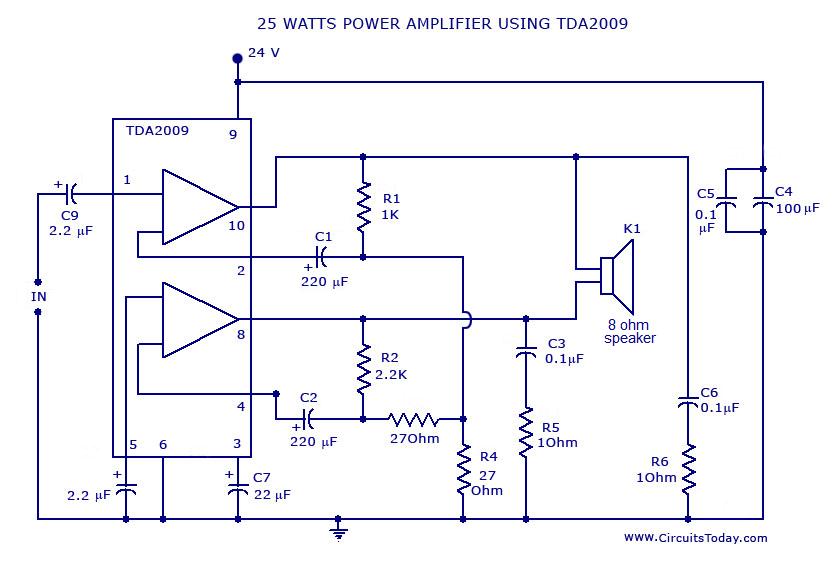
Here is the diagram of a 25 Watt power amplifier circuit made of TDA2009 IC. TDA2009 IC is a hi-fi Class AB stereo amplifier in a multi watt package. It is actually a dual audio power amplifier that is designed specifically for very good quality stereo applications. TDA2009 is used in amplifier circuits as the electronic components associated with the circuit are abundantly available and are economic too. The IC is integrated with two identical amplifiers that can produce an output of 12.5 watts per channel on 4 Ohms load. Here the two channels are bridged to get a single output channel weighting 25 W.
TDA 2009 IC has also built-in features such as short circuit protection, thermal protection, overload protection, etc using very low external components. The most interesting factor I see about this IC is that it does not require dual supply.
Components List
| Component | Specification |
|---|---|
| R1 | 1K |
| R2 | 2.2K |
| R3, R4 | 27 Ohms |
| R5, R6 | 10 Ohms |
| C1, C2 | 220uF |
| C3, C5, C6 | 0.1uF |
| C4 | 100uF |
| C7 | 22uF |
| C8, C9 | 2.2uF |
| Speaker | 8 Ohms |
| POT | 10K (For volume control) |
| Heat Sink | For TDA2009 |
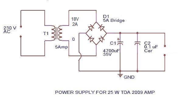
| Power Supply | 5 Amp Bridge Circuit |
Power Amplifier Circuit Diagram and Power Supply Circuit Schematic


Notes
- Do not connect more than 24 V to TDA2009.
- If 5 ampere bridge is not available make one using four 5 A diodes.
- Fit a proper size heat sink to TDA2009
- Do not operate the circuit without heat sink.
- For volume control connect a 10K pot
- All capacitors in this circuit must be rated above 25 V.
- Capacitors with + mark are electrolytic and that lead will be positive. Other capacitors will be normally ceramic. If there is exception that will be given there in the circuit or parts list.This law applies to all circuits in this site.

10 Comments
not worked with this diagram, but when i connect pin 1 & 5 as dual stereo input, it works fine
Why are the resistors R1 and R2 different values and why are the resistors R4 and the unnumbered resistor (value 270 ohms) connected between R4 and R2 different values and unbalanced? I would like to use it to drive two piezoelectric tweeters in series (one pair each stereo channel) – do the values need to be modified?
i am going to make an application which requires 4 speakers.
i am requiring a loud sound so need atlest 10 watt at the output
hence i am planning to use this tda2009 in sterio mode .
i will require to power up two tda2009 from same power source can you please tell me supply design reqirements and the circuit
what if i give only 10 volts as Vs to the tda2009 ic.how many watts will it output
can a 50watt rated tweeter work on this power
I connected this circuit as instructed however I am having A LOT of distortion and by a lot I mean the type of distortion that makes songs barely recognizable. Any help please?
Hi TDA2009 connect slider of the 10K pot to C1, one end of the pot to ground and the other end of the pot to signal in.
where can I mount the 10 k pot?
Hi,
I am from hyderabad, and i am new to this field, i want to build my RC receiver and transmeter for first RC plane.
plz can any one help me to build my own receiver and transmeter for my project
Regards
Prashant kumar
Definately cannot use a 4ohm spkr in bridged mode. The power supply shown is simply the wrong circuit for this amp. You need 24 volts at 2 amps, which an 18 volt AC transformer will supply.
Please note the speaker should be 8 ohms and the transformer rating should be 18Volt rms at 2 amps for the rated 25watts into 8 ohms with a good quality heat sink for the IC. (really a good quality amplifier with least distortion). with 18 volt 5amps with 4 ohms load the power delivered will be around 50watts. not recommended for this application. with the 24 volt secondary as shown the peak DC out put will be 34Volt which will destroy the ic instantly. with 4 ohms load in bridged configuration donot exceed 14Volt AC at 2amps, which will deliver 25watts into 4 ohms.
quero esqumas de circuito de potencia amplificador!