Before going to the depth of this article, there are a few basics that you should know. Especially, about the exact working of electricity.
Electricity mainly depends on three parameters. They are voltage, current and resistance.
These three parameters are related to each other and a proportional change occurs to these parameters, when a change is subjected to either one of them. Voltage is the parameter that makes the electric charge move. Current is defined as the rate of flow of charge through the conductor. Resistance causes a variation in the above two parameters, and hence the flow, and its value depends on the type of conductor used. The resistance also depends on the size of the conductor.
The relation between current [I], voltage [V] and resistance [R] has already been explained in my earlier post.
TAKE A LOOK : WORKING OF RESISTORS
According to Ohm’s Law
V = I * R
i.e, I = V/R
So, if the voltage is increased or the resistance is decreased, the charge flow will increase. If the voltage is decreased or resistance is increased, the charge flow will decrease.
This electrical charge when distributed to your home will flow through large circuit networks and also small circuit networks. This electrical charge is delivered to the homes using large wires that begin from a power plant or a sub-station. So, the whole circuit is supposedly brought home in a single piece of wire. One end of this wire will be connected to the sub-station and the other will be connected to the ground. The wire that connects to the power plant is called the hot wire and the other end is called the neutral wire. Since there is a voltage difference between these two lines, causes a voltage in the circuit. Thus, when the circuit is in the closed position, a flow of charge occurs. This flow of charge will be in the alternating mode as it changes direction constantly.
Need for Circuit Breakers
In every country the there will be a standard value for the voltage distributed by the power plants. In USA it is 120/ 240 Volts. Though this is a constant value, the value of the resistance and current will always vary according to our connections.
When we buy electrical components like bulbs and tubes, their company’s provide a standard resistance value for their effective working. This value, often referred to as the load, is the real reason for the appliances to work. When charge is give to an electric bulb, there occurs a flow which is resisted by the filament. Thus, the more the charge fights to move along, the more is the energy dissipated. This dissipation of energy is in the form of light, causing the bulb to glow.
When designing the electrical circuitry at home, special care is taken not to make contact between the neutral and phase. The charge is given to a component which acts as a resistor. This component limits the amount of charge to flow across. Thus, the components are designed in such a manner that the total voltage, current and the resistance across it are always constant. The ampere flow through the circuit is normally kept very small. If the current increases, more energy will be dissipated as the resistance will become low. Thus the extra heat may cause a fire.
There may be cases when such a hazard may happen. If the current through a component increases, the heat may increase causing the melting down of the wires inside. This causes a contact between the neutral and phase wires. It can also caused by unknowingly connecting both of them together. The fire thus produced may even cause the whole building to collapse. To avoid this, circuit breakers are used. Whenever the current across the circuit increases above a particular level, the circuit breaker comes into action.
Working of Circuit Breakers
As the name suggests, whenever the current level goes up, the circuit breaker breaks the connection between the appliance and the main voltage. Thus the hazard is prevented.
In olden days, a fuse was the most common type of circuit breaker used. The fuse consisted of just a thin copper wire that was plugged onto the circuit. The fuse is given in such a way that it carries the same current that flows through the rest of the appliances. When the current increases, heat increases and the fuse breaks through causing an open circuit. Thus the appliances are all safe. The only disadvantage with such a device is that it can only be used for one time. After its use, it has to be reinstalled.
The circuit breaker has more advantage than a fuse. It has a switch which goes off whenever there is extra current flowing through it. After each break, the switch has to be made on and thus continues its normal operation. There is no need of a reinstallation.
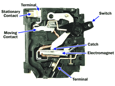
A simple circuit breaker consists of the following components.
- Switch
- Electromagnet / bimetallic strip
- Stationary Contact
- Moving Contact
- Catch
- Upper and lower terminal
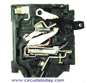
The switch is connected to the electromagnet with the help of a catch arrangement. In some cases a bimetallic strip is also used. The hot wire is connected to both the ends of the switch. During its normal working, the switch will be in the ON position. Thus, there occurs a closed circuit where the current flows from the lower terminal to the electromagnet and then through the stationary contact and out of the circuit through the upper terminal. The moving contact will be connected to the stationary contact.
If an electromagnet is used, an electromagnetic force is created when the electricity is passed through it. When current value becomes high, an electromagnetic force is produced which forcedly pulls down the metal lever connected to the switch. Thus the connection between the moving contact and stationary contact stops causing termination of electricity flow.
Take a look at the exact working of circuit breaker when the switch is in the ON and OFF positions.
If a bimetallic strip is used the passage of a high current actuates a thin strip to bend which in turn moves the metal lever.
After the circuit breaks, the working of the circuit breaker can be restored by turning ON the switch.


- Circuit Breaker in OFF position
The circuit breaker may be divided into several sub connections. A main fuse box panel may be installed, which includes any smaller circuit breakers which may include living rooms, upstairs, downstairs and so on.

1 Comment
when the circuit breaker “tripped”,to normalize it,switch the breaker first to the “off” position then switch to “on”.i guess, this is the proper way.