Description.
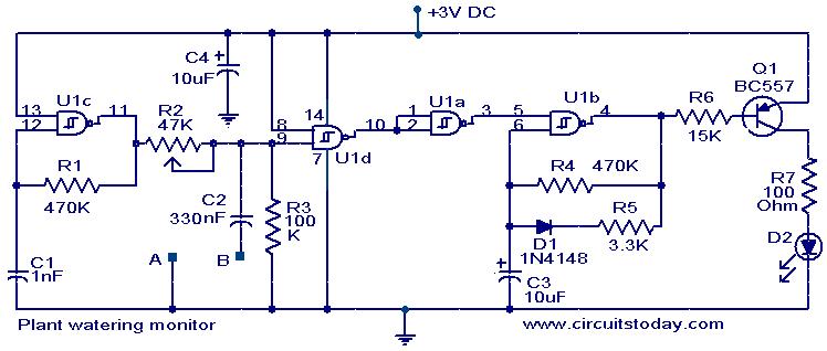
Here is a simple circuit that will give a visual indication when the soil water level inside your flower pot goes low below a certain limit.
The U1C and associated components are wired as an oscillator producing a 2KHz square wave. This square wave is given to one gate input of U1D via a variable potential divider former by R1 and R2.When the resistance across the probes A and B are low that is when soil moisture level is high, the C2 will divert the square wave to ground. The output of U1D will be high. The U1 A inverts this high state to low and so the IC U1B is blocked from producing oscillations. The LED will remain OFF. When there is no moisture across the probes, the C2 cannot bypass the 2KHz signal to the ground and it appears at the gate input of U1D.The output of U1D goes low, and it is inverted to high by U1A.The oscillator wired around U1B is activated and it starts oscillating. These oscillations are amplified by Q1 to drive the LED and LED starts pulsating as an indication of low moisture. Since square wave is used there won’t be any oxidation on the probes. The resistor R7 limits the current through LED and ensures a longer battery life.
Automatic Plant Watering System – we have designed a DIY moisture-sensing automatic plant watering system using YL69 moisture sensor and 8051 micro controller. The circuit is designed to turn ON/OFF a pump motor based on the soil moisture level.
Circuit diagram with Parts list.

Notes.
- Power the circuit from a 3V battery.
- Two metal wires 10 cm long and 5cm apart driven into the soil will do the job for probes.
- The probes are to be connected at the terminals A and B shown in circuit.
- Capacitors C1 and C2 must be polyester type.
- The IC U1 is a quad two input Schmitt NAND IC 4093.
- The sensitivity can be adjusted by varying the preset R2.
- Mount the IC on a holder.

12 Comments
Can you send me an image how to do the schematic on a bread board? I’ve been testing it, but I think it is not working. I need it for my project. Thanks
Hello,
Thanks for this. Question: are U1a-d all Schmitt NAND IC 4093s?
Also could I use 5, 9 or 12 V instead of 3?
Thanks
Shane
i would like to replace d2 and r7 w/ a 5v 6a relay is it possible?
i would like to replace d2 and r7 w/ a 5v 6a relay is it oissible?
Hi Mohit the notes under the diagram gives you the details of the moisture sensor.
I want to know about name of the moisture sensor because i need it in a project.
Hi Karthi C1 & 2 are non electrolytic C3 & 4 are electrolytic. Check the 2KHz tone between A & B by using a crystal or high impedance phone or through a PC ampli speaker. If it is OK. short A & B the LED should not flash open A & B link the LED should start flashing.
Hi Deepak the article explains the operation clearly. IC1-C is the 2KHz oscillator IC1-D conducts, when A & B resistance due to soil moisture is high. since one input is connected to Hi. the other input is oscillating in 2kHz hence the IC-D output also will be 2KHa oscillation. IC1-D output is inverted by IC1-A and fed to IC1-B. Initially capacitor side input to IC1-A is low hence output will be high hence the LED will be off. Once the oscillation is fed to the other input the output of IC1-A will go low and high as per the charging time of C3 and R4. As per this frequency the LED will blink.
sir can you please give detail explanation about the topic so that i could get proper explanation about the topic.
Are C3 and C4 capacitors polarised. I used 10uF, 63v capacitors.
My hardware circuitry isn’t working.
Is there any way that i can simulate it or troubleshoot?
Please help me to sort out this problem.
your circuit is verry usefull for my project,but can i know what IC that you have never mention the code or the number so that i can find it easyly.Anather question is which transistor can i replace for BC557 because in market verry dificult to find this transistor. please reply me as soon as posible, project is waitting to be demo. thanks on your circuit.
the type no of IC is given in the Notes
you can use BC157, or BC177 instead of BC557.In fact any common PNP transistor will do the job for Q1
A 74HC132 is a good quad, two-input, Schmitt NAND IC to be used for U1.