Description.
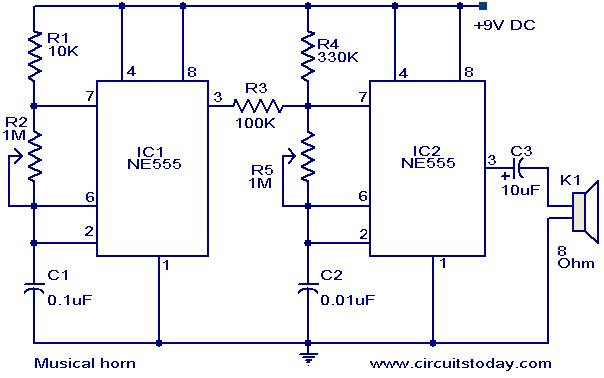
Here is a simple circuit diagram of a simple musical horn using two NE555 ICs. Two ICs are wired as astable mutivibrators. The output of first multivibrator is given to the discharge (pin 7) of the second astable multivibrator. The combined effect of the astable multivibrators produces a musical tone at the output.
Circuit diagram with Parts list.
Notes.
- The sound effect can be adjusted by varying the POTs R2&R5.
- The speaker can be a 8 Ohm tweeter.
- The circuit can be powered from a 9V PP3 battery.
- The ICs must be mounted on holders.
- All capacitors must be rated 15V.
17 Comments
The sound generated by this circuit at 9 Volt supply is very feeble. How to increase its sound .Is it possible with a single transistor based amplifier ? If so please help me to have such a circuit at the output of 2nd 555 IC instead of feeding a loud speaker. hope I will receive your reply in tis. Kindly help.
I have assembled this circuit on a bread board first in which I could get only clicking sound then I have soldered the circuit in a general purpose pcb and the circuit functioning real train horn. I have used one 8 ohms tweeter and another one from a broken toy. The sound from 8 ohms 2 inch speaker was not that much appealing whereas the sound from the speaker of toy ca with funnel attached has produced real sound of a train horn. Thanks for such a circuit. If I get pcb for this from you I am ready to buy a minimum of 10 nos. a line from you will be appreciated
please send me sound of this circuit
I’ve tried to build this circuit, but have failed. When I powered it on, it sounded a bit then stopped working all together. I built this on a breadboard. I noticed that it requires holders. But holders are used when you either need to easily switch the chip out or want to prevent heating the chip when soldering. Do you need a holder for the 2 ics even when mounting on a breadboard? If not then what did I do wrong? Thanks to anybody who answers
My programmer is trying to convince me to move to .net from PHP. I have always disliked the idea because of the expenses. But he’s tryiong none the less. I’ve been using WordPress on a variety of websites for about a year and am anxious about switching to another platform. I have heard very good things about blogengine.net. Is there a way I can transfer all my wordpress posts into it? Any help would be really appreciated!
please, send me working of this circuit
Hi sir,
I am working on clap switch circuit and circuit competition will be on 15 April.
Specifications are
“make clap switch circuit using 741 with 9v battery which activates on clap sound.the circuit which detect the faintest clap will be winner.you may use other ICC’s along with 741.
I need more description of this musical horn project….will u b able to snd it to me???
hello Seetharaman,
I have forwarded my email ID,
thanks for all ur help.
regards
Hi Rohit my email id is seethasub@hotmail.com you can address your requirements.
soon i will mail you once i get a mail from you.
Hello seetharaman,
I didnt know where to address it, hence i picked this aritcle.
Is there a circuit diagram for clap switch activated LED (Preferably 20-30LEDS) mains opreated
Thanks for all your Advice.
Hi Zohaib lots of circuits have appeared in Circuits today, you can use one of them or kindly post your requirement
hi, help me to design battery charger please.
hiiiiiiiiiiiiiiiiiiii circuit working very nice thankyou
hi,i am from bangladesh,want a simple and easy mp3 circuit diagram include fm radio,for hobby,which will make easy in home…………..
Can anyone please design a circuit to supply 6v on a clap i.e a clap activated 6v power supply.
6v output should be continues and show proper relay connections
very good one ,sir
i m one student of tech in my
anmar ,asia
i interest more on wireless control n robot tech
thank