Description.
When there is a fire breakout in the room the temperature increases. This ultra compact and low cost fire alarm senses fire breakout based on this fact.
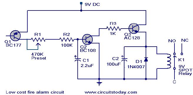
Transistor BC177 (Q1) is used as the fire sensor here. When the temperature increases the leakage current of this transistor also increases. The circuit is designed so that when there is an increase in the leakage current of Q1, transistor Q2 will get biased. As a result when there is a fire breakout the transistor Q2 will be on. The emitter of Q2 (BC 108) is connected to the base of Q3(AC 128). So when Q2 is ON Q3 will be also ON. The transistor Q3 drives the relay which is used to drive the load ie,light,bell,horn etc as an indication of the fire. The diode D1 is used as a free wheeling diode to protect it from back EMF generated when relay is switched.
Do you need to get a better understanding on the basics of electronics? We have listed 4 of the best books to learn the basics of electronics. They are written by famous electronics authors like Forrest M Mims, Charles Platt, and so on. You can go through the reviews and buy them online here:- 4 GREAT BOOKS TO LEARN BASIC ELECTRONICS.
Circuit diagram with Parts list.
Notes.
- The Preset R1 can be used to desired temperature level for setting the alarm ON.
- This is not a latching alarm,that is;when the temperature in the vicinity of the sensor decreases below the set point the alarm stops.
- The circuit can be powered using a 9V battery or a 9V battery eliminator.
- All capacitors are electrolytic and must be rated at least 10V.
- The load can be connected through the C,NC,NO points of the relay according to your need.
- The calibration can be done using a soldering iron, and a thermo meter. Switch ON the power supply.Keep the tip of soldering iron near to the Q1. Same time also keep the thermometer close to it. When the temperature reaches your desired value adjust R1 so that relay gets ON.Done!
91 Comments
Where do i place the speaker.. which is apparently gonna be my alarm.. there is nothing in the circuit diagram that indicates about the alarm and sensor.. plz help.. thanks 🙂
hi
I was going through this ckt diagram and I have few queries. Can you help in sorting out these
1) its mentioned that The emitter of Q2 (BC 108) is connected to the base of Q3(AC 128). but I think as it shows it is npn transistor so according to diagram collector is connected to the base of Q3
2)And we applying 9V dc so I just want to know the polarity of the battery like the positive terminal is towards Q1 or Q3 because the emitter of Q1 and collector of Q3 they both should have more POsitive compare to base to conduct .
can any body reply as soon as possible
Sir,
I am willing to learn about this project more deeply.Please help me.I have know about the schematic circuit diagram and also the PCB designs..Thank You…
pls i need the video of the circuit
can i use 12v relay??????? please help me i’m gonna make this as my project thanks!!
can you sent me a proposal that you did for this project cuz i want to refer how to do it…
can i use 12v relay??????? please help me i’m gonna make this as my project
Can you send the abstract for this experiment
Can you send the abstract
sir what is mean by NO NC and resistance r1 whts its value?
NO means normally open contact(when relay is de-energised this contact will be open when the relay in energised it will become close contact) Similarly NC means normally closed contact will go open when relay is de-energised. R1 os a variable resistance which can be varied from 0 ohms to 470 kilo ohms as per required temperature level. It will be a practical adjustment
why capacitors are used?
can u help me to write the project report on fire alarm using thermistor??
Can I download the details of this project.where is the link?
Can i use BC107 instead of BC108? i couldn’t find BC108 in my country.
from the datasheet of both transistors the only difference seems in the current gain, is it gonna be ok if BC107 used in this configuration?
Thank you so much in advance
hi, am taking this as my project. Please kindly send me the design and whole complete circuit diagram plz. And specification if possble. Thx in advance
please help me with the circuit i still cant get the output even after changing the q3 transistor the dead line of the project is closing
no full circuit provided…
at what temperature the fire alarm senses
can we replace ac128 with any pnp transistor like bc557??
AC128 is wrongly shown as NPN transistor it should be pnp and its emitter should go to + and collector should go to the relay. You can use any switching pnp transistor like S8550, 2N2905, BD136. BC557 cannot give the required drive current.
Hi Alok yes you have to leave base open as the temperature increases its collector emitter leakage current will increase and that will trigger the alarm. The basic principle used here is the CE leakage current vs temperature characteristic.
Should we leave base pin of bc177 open….???
what does relay in low cost fire alarm?
diagram of fire security alarm best price
i am very thankful
Q3 should be PNP collector to relay and emitter to +9volt DC. copy Q1 and paste on Q3.
Set the alarm just to reset in shade with R1 and use direct sun light on Q1 to activate the alarm.
it’s really working.
sir,at how much resistance value should i keep the potentiometer at normal room temperature??and q3 should be npn or pnp?
sir
When I want to try the project ?
How do I make the place its elevated temperature?
please i need some guidelines on how to make this project,i choose it as my project topic…thanks
SIR IAM DOING A PROJECT FOR MY SCIENCE FAIR IAM TRYING MY LEVEL BEST
I am interesting to make a project this experiment .
Can u help me to make this project……………..
sir,
i am doing this as my mini project. kindly send me the design of the circuit and working to kavyakrishnan1992@gmail.com . also where should base of Q1 be connected? kindly reply .. its urgent
Set the alarm just to reset in shade and use direct sun light on Q1 to activate the alarm.
Hi, am in Nigeria and I appreciate this project… Any mini soundless generator project available? I will use this project of yours as 1st alternative project but I need more just incase my supervisor doesn’t approve it. Thanks
sir,its not working and i replace q1 with bc307.is it ok?what do u mean on adjusting the potentio sir,is it a full volume?pls reply
Hi,
If I am not wrong, the potentiometer here adjusts the sensitivity of the circuit. Since it biases the transistor Q2 from the output of Q1. It means that, by adjusting this potentiometer (a variable resistance) you can change the sensitivity of the circuit (not full volume). For example, if the circuit is made more sensitive, it will go on for a very less amount of fire etc.
i tried this circuit 5 times but i fail…my project deadline is near…
sir i choose this as mini project for TE electronics engg so please give layout of circuit and also tricks to run it
the circuite is not working. why? sir..
May be you wired it wrong. Check if the transistor pins are in correct position. Misplacing the transistor pins is the most common mistake which goes out unnoticed. Adjust the preset properly.
where will i put the load sir?is it on the c,nc?or in the c,no?tnx
well, as said in the above post, it depends on your need. If you going to connect a buzzer simply, just wire it in the NO pin.
It would be better if you provide a video how to make a fire alarm…
Waise its gud..
is the low cost fire alarm effective?
from the description: transistor Q2 will be on. The emitter of Q2 (BC 108) is connected to the base of Q3(AC 128).
question:y is it that the emitter of Q2 is connected to the ground not on the base of Q3???
Thanxxxx dude…
Very good work well done.
Sir how much do you think will I spent for this project?,,is Q3 here a PNP transistor?..specifically what transistor is that so that i can canvass if there is any,,,tnx sir
I want the detailed explantn abt this and i liked it and i need it urgently!!!!!plz do it as soon as possible
in the diagram..where i will connect the base of Q1?
base of q1 is the heat sensor…lol
Hello! Sir the circuit diagram shows to connect the connect the collector to the base of Q3, while in description it says to connect the emmiter of Q2 to the base of Q3. Will u kindly correct it
thnx!
Hi guys.. the circuit may work but take note you can’t use it as a standard fire alarm in rooms especially ventilated one,you need to heat the room first or the room is already on flames to activate the alarm and you can’t control the fire anymore. For kitchen you can used heat sensing alarm like this and other fire alarm circuits using heat sensing component such as thermistor where smoke alarm will be not suitable but for rooms use smoke alarm which is cheaply available for safety reason.
hi!
it’s realy works.
hey can u plz send a video clip. or detailed explaination on how to carry out the this project. urgent.. reply plz..
hi!this is swapnali(TE E&TC)student..i want miniproject with report or with more ideas.so please sir help me…
it will be helpfull 4 us if u provide a vedio
did u get the video????
hmm.. u r right
Hi Zack you can replace it with 2N2905. the symbol shown for Q3 is wrong it should be similar to Q1 as it is also a PNP transistor
sir i hv try to find Q3 AC128 but unvailable,can i change that AC128 to another trans?
help pls
can i supply this ckt by 24 volts? and regarding the n.c – n.o output of this ckt is it respect to ground or to the com. terminal of the relay.
hi, i want to know how to connect the detector to the ckt. from the base of bc177 respect to the ground?
Hi Elgardo you are right Q3 is wrongly shown as NPN transistor it should be PNP with collector to relay and emitter to positive. otherwise the circuit is correct and will work as per the design.
Sir,
I am studying the circuit diagram and I got confused.
Is it the collector of Q2 will be connected to the base of Q3? (It says on the text :The emitter of Q2 (BC 108)is connected to the base of Q3(AC 128).)
Or is this a typographical error?
Please help.
Sir i need the pcb layout of this project…will you pls email it for me,,,tnx a lot 🙂
Sir,
I am from India,
I want to start my own company based on Development Of projects….
please give me some guidance and valuable time if possible then mail me on
dhananjay_gangapurkar@yahoo.in
Thanks For reading…
Keep saying some good thought for me………….
it’s very nice…!
where should base of bc177 trasistor connect
Hi Sarah for fire alarm DC is preferable, so that they can work during power cut also. You can use rechargeable batteries with a suitable charger for 9 volt. this will be fail safe, whenever power supply is available it will be charging the battery as well powering the alarm. during power failure the battery will take over.
Sir is it really working?..if i change the Q3,,i will be making this as my project in ECE 111,,,,Iam an Electronics eng’g student,,tnx
are you done in your project?i dont get it..pls give me the correct diagram..
is there any other way to give 9v instead of using transformer
sir i didn’t understand the terms NO,NC, C; and the component K1, and is R1 is a rheostat or resistior, waiting for your reply
i didn’t under stand the R1(it is a resistor or rheostat), what are the components used as K1 ,NO,Nc,C
sir i tried your ckt…but after lots of attempts…still the ckt is not responding to the heat.when i connect to the supply the relay gets on (showing that current is flowing through the ckt)..but after that it doesnot respond to heat at all.please help!
This circuit will not work properly as soon as you plug it. You need to calibrate the circuit before using. Calibration can be done by adjusting the POT R1.
I tested this circuit and there is no problem with it.
sir…wat is this preset r1?is a variable resistor or potentiometer?can you pls send me the correct diagram and detailed description..?pls
sir i am from bangladesh.your circuit is very easy to establish.but i face a problem to find transistor Q1(bc177).its unavailable.equivalents of this transistor bc178,bc179 are also unavailable.please help me to find another transistor.
BC 477, BC478 etc can be used in place of BC177
hi the circuit was nice but i have a small doubt that is “what is the relation(formula) between Temperature and Resistance R1”.
i mean how can we know the resistance(R1) value for our desired temperature.
hi sir..
im quennie
from the philippines and
i just want to ask if you have
a diagram of the ic you used..
i mean if you have some diagram
to guide on so that i can place the materials in their
right position and place..
thank you sir
and god bless!
hi…areu donewith thisproject?pls xplain methe correct circuit pls…
I think your article very useful for people who want to know about alarm work especially electronic
Hi deepak,
which transistor you used in place of Q3 ?
sir the circuit u provide for fire alarm is not working according to the circuit.
actully I am a student and working on this fire alarm project. I joined all the connections according to ur circuit but it is not working plz help me…
at place of Q3(AC128)i used another transister like the same of this.
plz sir help me to complete my project ..
waiting for reply..
thank you.
hi…we are abeg combne in the fir fiting in k.s.a.
we wnt to ask abawt low cost fir alarm braes lik thts model in yor websitid
may ourdr is:300 panel 2zon
200panel 4zon
100 8zon
50 12 zon
50 18 zon
3000 smok detecotor
1000 hetar detecotor
1000 strop siren
500 alarm beel
we are wating yor bris in thes E MIL:HATIM_ALSAFI@MAKTOOB.COM
fax namber:0096677222277EXT106-105
thnk you….
meneger: hatim al safi
hi…we are abeg combne in the fir fiting in sawdi arebia.
we wnt to ask abawt low cost fir alarm braes lik thts model in yor websitik
may ourdr is:500 panel 2zon
500 panel 4zon
300 8zon
200 12 zon
100 18 zon
5000 smok detecotor
2000 hetar detecotor
2000 strop siren
500 alarm beel
can yuh give me the block diagram please if possible