Description.
This timer circuit can be used to switch OFF a particular device after around 35 minutes. The circuit can be used to switch OFF devices like radio, TV, fan, pump etc after a preset time of 35 minutes. Such a circuit can surely save a lot of power.
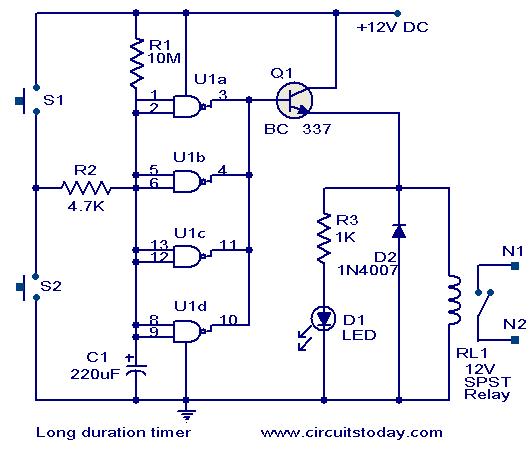
The circuit is based on quad 2 input CMOS IC 4011 (U1).The resistor R1 and capacitor C1 produces the required long time delay. When pushbutton switch S2 is pressed, capacitor C1 discharges and input of the four NAND gates are pulled to zero. The four shorted outputs of U1 go high and activate the transistor Q1 to drive the relay. The appliance connected via the relay is switched ON. When S2 is released the C1 starts charging and when the voltage at its positive pin becomes equal to ½ the supply voltage the outputs of U1 becomes zero and the transistor is switched OFF. This makes the relay deactivated and the appliance connected via the relay is turned OFF. The timer can be made to stop when required by pressing switch S1.
Circuit diagram with Parts list.
Notes.
- Assemble the circuit on a good quality PCB or common board.
- The circuit can be powered from a 9V PP3 battery or 12V DC power supply.
- The time delay can be varied by varying the values of C1&R1.
- The push button switch S2 is for starting the timer and S1 for stopping the time.
- The appliance can be connected via contacts N1 & N2 of the relay RL1.
- The IC U1 is 2 input quad NAND gate 4011.
30 Comments
admin
can u plzzzzzzz tell me how to operate this ckt
Plzzz some one can explain me the above ckt (how the capacitor gets discharging)
sir,how to connect that circuit diagram,plz reply
Thanks for this kit, but I think there is some problem with the connection for BC337, I think it must connect the emitter to the ground & the collector to the relay circuit.
Please can you check & confirm if I’m right or wrong.
with respect
Sallam
hello, the cct is very educating. i need a timer cct that is capable of delaying up to 6 – 7 hours then switch a dc motor for about 5min then switch off for another 6-7 hours then the circle continues. i intend to use the cct in fish feed control. i will prefer a transistor cct to cmos. but if only the cmos cct are available i will greatly appreciate them.
thanks.
Hello
I am looking for the long duration timer for DC power supply up to 2000 hrs.
Regards
Shridhar
I am looking for a circuit which is both clock 5 1/2 digit (with seconds) and stop watch in one. I have to use in running events. please guide and if possiable email me the circuit diagram and pcb layout.
Hi Sir,
I am looking for a circuit which can switch on a 230V pump to water the plants when out for vacations. The circuit should switch off after around 5 minutes. This would be a great support.
Thx
Amit
amit.maheshwary@fluor.com
it is good circuit. But is .’does’nt stop automaticaly’
i need this type circuit
i want to know where to connect the relay in the device..? ASAP!!! thanks in advance
Hi sir, i am looking for distance bombs detector circuit diagram for security purpose ,thanks.
i want to know the application of timer circuit in fans and radio
Hello Seetharaman,
Iam looking for a similar circuit, but the timer circuit should work for about 8 to 12 hours. I made a LDR operated circuit (for outdoors), but where i come from, they have a standard type of LDR and this is like if u take a LED real close, (about 100mm)the LDR switches off the circuit and also the weather these days is very cloudy. hence with ur above circuit and suggested modification, should be able achieve what iam looking for.
Thanks for all your support.
regards
Hi Sakib change Q1 to PNP transistor BC327. emitter to positive base to U1 and collector to relay it will become alright.(before change, switch on status for the relay is on, it is now change to off)
PROBLEM :please help who had made it.
I had made the ckt but there is an prob when the ckt power is off and come back again b4 i switch on the s1 of the ckt the ckt goes to on (as like i switch s1)the relay start to operate.
Ques: when i will apply it to any device it will auto on when the power gone and come again.
THANKS……………
I need electronic circuit for timer switch use tool my school, please send for my. thank
Hi every body i from Mauritius i prepare a chance over panel for the sarvay room i used 24 Hr time and contact to control two A/C units each A/C has to work fro 2 Hr alternate .
I want to disign one electronic card to do this fuction.
I need a timer for 2 or 3 hr
Thank Bye
hi..It’s really a good design.
n i wanna thanks to you for this job..
Hi Brian the switches S1 S2 are bell push switches. (push to on release to off – not latching type))
Is anyone still out there?
Can you please tell me what causes S2 to release or is it just a momentary switch.I assume you don’t have to manually release it as this would defeat the whole purpose.
Thanks
Hi admin
1.Can i use this circuit in two appliances?what should be the apms required?
2.For varying the time delay?what will happen if I increase or decrease the value of C1 and R1.
3.Do the C1 and R1 have both relation in varying the time delay or as per individual?
thanks in advance,
philippines
Hi admin,
1.can I use this circuit using two appliances.what AMps is needed for that?
2.For varying the time delay what will happen if I increase and decrease the value of C1 and R1?
3. If C1 and R1 have both relation in varying the time delay?or as per individual?
thanks and advance
Hi admin,
i have an exhaust fan and a soldering iron.I want them automaticaly turn off. can you discuss the wiring diagram of connecting the circuit above to appliance and to AC supply.
thank in advance.
Hi Shaaban are you interested in controlling the staircase lights of your building. ou want it to light all night or when some one switches on should go off after 5mts or so. kindl send the actual requirement.
Please do you have Circuit diagram with Parts list for timer relay 220V, To control the lighting 10 lamps during the ups and downs in the building.
Thank you very much
Shaaban Al-Shazly
Cairo, Egypt
regards!
i wanna switch off my ceiling fan after one or two hours, when i sleeps!
i don’t know how to do that to my ceiling fan!
is this circuit will solve my problem or not? then how?
help me experts!!
Chris
I know it’s a bit late but yes you could. Easiest way would be to replace R1 with a 10M pot.If this doesn’t prove accurate enough then you could change R1 to a 5M pot and C1 to 100micro farads.
Tis is okay.Could you give me details on long distance IR circuit.
Please advise me if I would be able to adjust the time delay to 35 seconds (Thirty five seconds)on this project or have you another design.
Frankly I want the unit to switch ON again after 30 seconds…..from the time it was disconnected.
Thank you kindly
Chris Halgryn
Fjord Electronics & Designs inc.,
Auckland
New Zealand
samshith triprayar, you can have a relay of dual contact and use one contact instead of S2. This make alternance. S1 as described by designer it not so necesary if you want it be working continously.
What I need is a similar desing but where I can change or select time off and on independentily.