In this project, we’re building a simple Lamp Flasher circuit using NE 555. A lamp flasher is nothing but a lamp dimmer circuit – where the lamp is turned ON/OFF at set frequency or time intervals. We’ve designed this circuit using the most popular and common components like the NE/SE 555 IC. Let’s begin our journey to build a lamp flasher circuit using 555 IC.
Description
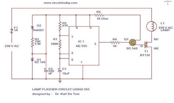
This is the circuit diagram of lamp flasher operated from mains. By this you can flash up to 200 Watt lamps at rates determined by you. IC NE555 is wired as an astable multivibrator for producing the pulses for flashing the lamp. The flashing rate can be set by the value of resistors R2 & R3.
Diodes D1 & D2 provides a half wave rectified regulated supply for the IC. Transistor T1 is used to drive triac and triac BT136 for driving the load. Resistor R4 limits the base current of Q1.
Flashing Circuit Diagram & Parts List
Notes
- Assemble the circuit on a good quality PCB or common board.
- Connect a 100K pot instead of R2 if you need frequent changes in rate.
- Many parts of the circuit are live with potential shock hazards.So please be careful.
- As usual use an IC holder for mounting the IC.
Modified Circuit

30 Comments
What are the replacements for BZ 148 zener diode?
hi can any body tell me that can i use bta41 insted of bt136
hi 555 part not powered ,ac hot line shd given 2 diodes ( IN 4007) + side.
The circuit contains a mistake. As it is drawn, it will never work!
Hi Gelie have you used the modified circuit. your zener diode and transistors are the correct equivalents.
why is that my circuit did not work?? i used 1n4738 instead of bz 148 and 2n3904 instead of bc548 does this affect the output of the circuit??
Hi Harsh even without this capacitor the astable will work.
Hi!
In the above circuit a capacitor is missing. Astable multivibrator circuit is incomplite.
U must connect a capacitor of 10 nf(63 volt) ceramic between terminal 5 and the ground of 555 timer.
hi guys
thish circuit works only in half wave mode
and in other half sine wave the triac comes off
this use the triac as a trimister(SCR)
if i wrong say me explaine it for me
i test it in other circuits
it imposible that run a triac with direct curent
u most connect the gate to the m base withe full wave connection.
bye
Hi Kkhairul your IC and trasistor might have got protected due to R3 10k ohms which has limited the current to 25mA . if they are found healthy you can use them
Hi Seetharaman,
I run my circuit sometimes using this FALSE zener diode 51V instead of 5.1V before. Can I use my IC, transistor and triac anymore?
Hi Khairul C2 is the timing capacitor C1 is filter capacitor. only timing capacitor requires the change for higher frequencies. Use a pulse transformer direcly between pin 3 and 8, [(used in xenon strobe trigger for getting high voltage spikes(pulses)]by deleting triac and associated circuit. You can use any zener from 5.1 volt to 6.8 volt or BE junction of BC148 transistor in reverse biased condition.
Forgot to mention that, I was not able to find zener diode BZ148 specs. So now I’m using 51V zener diode. Does it affect my circuit too?
Forgot to ask. If I need this lamp to have a high voltage for each pulse produced, what can I do to modify it?
Hi Seetharaman,
do I need to change C1 to 1uF, or C2?
Hi Khairul you have remove L1 qand connect the halogen lamp in that location. (MT2 and live of the supply). neutral is common connected to IC Pin 1 and Triac Mt1. Power of the lamp multiplied by the flash on duration is the energy consumed. To vary duty cycle increase R2 to 100k, to increase frequency reduce capacitor value to 1uF to have a higher range on and off time increase the rheostat to 1M.
Hi Seetharaman,
Right now I’m using a halogen lamp of 50W as an output. I really need to calculate the energy released by this lamp. Therefore I want its frequency so that I can obtain time. Power of lamp divided by flashing time will give the desired energy right? How can I check its flashing frequency? I’m tapping at M2 triac and also common. Is it correct? When I turned the rheostat, the frequency were changed only around 31-33Hz. How can I get a much higher frequency?
Hi Khairul it should work if not due to your variable resistance. you can use a frequency meter at pin 3 of the IC and common (pin 1 of IC)
Hi Seetharaman,
Thank you for your info. How could I check the frequency of the output if I’m using rheostat instead of 47K of R2? My lamp is not flashing accordingly as I turn the rheostat. Is it because of my rheostat?
Hi Khairul the D1 diode is a zener diode. The base emitter junction of BC148 connected in reverse-biased condition. D1 is an isolating diode / rectifying diode for giving DC to the IC and AC to lamp circuit.
Hi Seetharaman,
What is exactly D2? I want its specifications. Could you please help me. I didn’t find BZ 148.
Hi friends
D2 anode should get connected to fuse not to BZ148. D2 is a half wave rectifier, R3 will drop the voltage BZ148 is the shunt regulator. R5 can be 1/2 watt.
Yes, I can not understand also how the circuit rectifies. How much wattage is the R5 (10 Ohms)valued? Is it possible that the anode of D2 will be connected to the fused line, and the junction of D1 and R3 WOULD be connected to pins 4, 8 of IC1 along the resistor R2?
Awaiting for your very valued feedback please.
Pls recheck ,supply for 555 not available.
Where is the VCC power (+) for 555 ?
D2 & R3 is short ?
yes.. I think D2 Anode should be connected to upper line .not to the +vcc of IC.Then it forms a half wave rectifier.and regulated by D1.
I fail to see how you get the mains to the D1, D2 circuit for rectification???? It looks like D2 in series with R3 is shorted out?!
information about lamp flasher using 555 timer
all information about lamp flasher using 555 timer
all information about lamp flasher circuit using NE 555, Design by Dr Kun De Tom