Interfacing stepper motor to 8051 microcontroller.
This article is about interfacing stepper motor to 8051 microcontroller. Many guys were asking here to show how to interface stepper motor to 8051 microcontroller. I think this is the time. Stepper motors are widely used in industrial, medical, consumer electronics application. In simple words, anywhere precision rotation or positioning of an object is needed.
Stepper motor.
Stepper motor is a brush less motor which converts electrical pulses into mechanical rotation. As the name indicates it rotates in steps according to the input pulses. A stepper motor usually have a number of field coils (phases) and a toothed rotor. The step size of the motor is determined by the number of phases and the number of teeth on the rotor. Step size is the angular displacement of the rotor in one step. If a stepper motor has 4 phases and 50 teeth, it takes 50×4=200 steps to make one complete rotation. So step angle will be 360/200=1.8°.
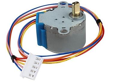
The stepper motor we are using has 4 poles and a 1/64 reduction gear mechanism for increasing torque. The step angle of the motor is 5.64°. But when considering the reduction gear, the step angle of the output shaft is 5.64/64°. The internal schematic of the stepper motor is given below.
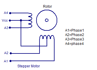
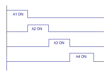
The stepper motor is rotated by switching individual phases ON for a given time one by one. The sequence is given in the graph below.
Circuit diagram.
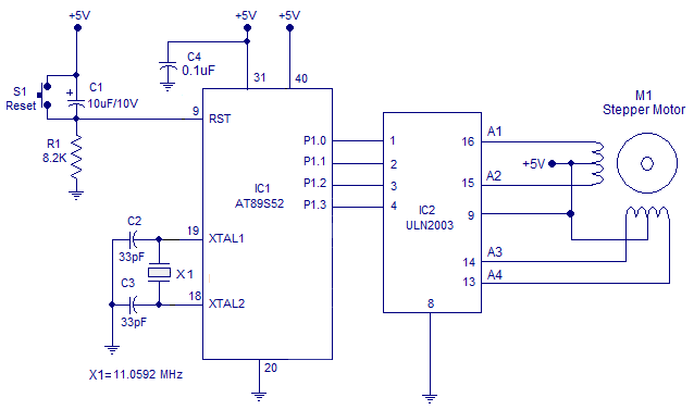 The circuit diagram for interfacing stepper motor to 8051 is shown above. P1.0, P1.1, P1.2 and P1.3 pins are used for controlling the phases A1, A2, A3 and A4 of the stepper motor respectively. ULN2003 is used for driving the individual phases of the stepper motor. ULN2003 is a darlington transistor array used for driving high current loads such as relays and motors. ULN2003 has 8 individual channels each with 1A capacity. The channels can be paralleled to increase the current capacity. Each channels are fitted with individual freewheeling diodes. The ULN2003 is operated in current sinking mode. Each channel is activated by giving a logic LOW at the corresponding input. For example if we make pin 1 of ULN2003 LOW, phase A1 of the stepper motor gets switched ON.
Program.
A1 EQU P1.0
A2 EQU P1.1
A3 EQU P1.2
A4 EQU P1.3
ORG 00H
MOV TMOD,#00000001B

MAIN:
CLR A1
ACALL DELAY
SETB A1

CLR A2
ACALL DELAY
SETB A2

CLR A3
ACALL DELAY
SETB A3

CLR A4
ACALL DELAY
SETB A4
SJMP MAIN


DELAY:MOV R6,#1D
BACK: MOV TH0,#00000000B
      MOV TL0,#00000000B
      SETB TR0
HERE2: JNB TF0,HERE2
      CLR TR0
      CLR TF0
      DJNZ R6,BACK
      RET
END
The program first clears P1.0 for activating phase 1 (A1) of the stepper motor. This condition is maintained for 65mS and then P1.0 is set for deactivating phase 1 of the motor. Then the same process is repeated for the port pins P1.1 to P1.3 and the entire cycle is repeated over and over to make the motor rotate in the clockwise direction.
Timer 0 of the microcontroller is configured in Mode1 for producing the 65mS delay. 65mS is the width of each control pulse.
1 Comment
Thanks for the effort but ULN2003 act as an inverter so a HI at the input will activate the output