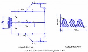
How to make a full wave rectifier using SCR ?
For full-wave rectification two SCRs are connected across the centre taped secondary, as shown in figure-a. The gates of both SCRs are supplied from two gate control supply circuits. One SCR conducts during the positive half cycle and the other during the negative half cycle and thus unidirectional current flows in the load circuit. The main advantage of this circuit over ordinary full-wave rectifier circuit is that the output voltage can be controlled by adjusting the gate current.

Now if the supply voltage v = VMAX sin θ and the firing angle is a, then average voltage output will be given by the expression
Vav = VMAX / ∏ (1 + Cos α)
That is, average voltage output of full-wave rectifier circuit is double of that of half-wave rectifier circuit, which is obvious.
Iav = VMAX / ∏RL (1 + Cos α)

7 Comments
i am going to designe full wave center tapped rectifier and i dont know how to determain the alpha angle in lab i mean in real i know that i can assume it in paper but i dont know how to detemain it in the real experiment
from the circuit shall i promoted with two outputs…..
Please specify the component details
Design of phase controlled voltage regulator using full wave recitifier and scr.
Bogus circuit.One has to use 2 batteries to control the Dc. Is it practicable?
The ful wave circuit
How do you calculate the resistive and capacitive values to get the firing angle? Is the resistor connected to some sort of voltage?