Description.
A simple telephone transmitter circuit that is ideal for transmitting the telephone conversation through small distances.The circuit is very simple and uses only few components.The entire circuit can be easily included in the telephone itself or in the junction box.The circuit is powered from the telephone line itself.
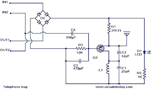
The transistor Q2 is wired as a a Colpitts oscillator to produce oscillations in the FM transmission band.The audio signal from the telephone line is coupled to the the base of Q2 to obtain the frequency modulation.The LED D1 acts as a power on indicator.
Circuit diagram with Parts list.
Notes.
- Any radio frequency PNP transistor like A933 can be used for Q2.
- For L1 make 8 turns of 0 .6mm dia enameled copper wire on a 3.6mm dia steel bolt.
- For antenna use a 15cm long 0.6 mm dia copper wire.
19 Comments
There is no In1 and In2 and Out1 and Out2 on a telephone line.
There are ONLY TWO WIRES, NOT FOUR!
Not even three.
hi
please send me full discription of this circuit function
thank you
hey can u send me the detailed description of dis circuit its unable to understand d working with such less info. can u do it asap??? i wud lyk to do dis as my project please..
plz give a detailed description of the circuit..how to connect with telephone..is it possible to connect with a mobile or wireless phone?
HI !
Pliz wd u send me a clear discription of this whole circuit. Thnks
Plz the description is not enough to understand the working of this.Is there any recevier required for convarsation or what?I cant understand.Plz send me complete discription of this circuit.thanx
How to make turns, over or around the bolt.
Hi Segzy The bridge rectifier circuit will be completed through the connected telephone instrument. if the instrument is not connected then the circuit will not work.
Is d2 bridge retifier?where is Q2?wher wil in and out go?
Hi Elgardo Disconnect your incomming line to your telephone. connect Out 1 & 2 to your telephone. connect the incomming line to In 1 & 2.
Hi Seetharaman, can you e-mail me the drawing how to connect the IN1,2 and The OUT 1,2 for clarification? i am slow on this connection.
Thanks
Hi Bryce the signal available on the telephone cable will be transmitted. (The coversation – signal from both the caller and called ones mic will be transmitted)
is the telephone insterment the mic
Hi Bryce In is to be connected to telephone line and out to the telephone instrument.
Range will be around 100feet.
what is the wireless range of this circuit
what is IN 1 and 2 ,and OUT 1 and 2
Its designed by our logo designer! We will be having a fresh look very soon!
regards & thanks for adding to the feed reader.
Good post, I like your writing style! I’ve added https://circuitstoday.com/ to my feed reader, and will be reading your posts from now on. Just a quick question – did you design your header image yourself, or have it done professionally? If you had it done by a professional, who was it?