In this article, I would like to introduce you to the concept of interrupts, how interrupts work, vector address, interrupt priority and how to write an ISR (interrupt service routine).
“Interruption” in English language means a deviation from the normal routine. We know the processor is always busy executing some kind of instructions. What if there occurs an urgent condition that we need to pause the processor from its current activities for some time and make it execute/do something else? Also we need to resume the processor back to its operations after executing our “urgent condition”. To meet such a demand, 8051 micro controller has got a system called “Interrupts”. An interrupt is usually a signal from the external world or a command from the internal program (called software interrupt), which forces the processor to pause its current activities and then jump to another location to execute another set of predefined activities. While doing so the processor will save its currents status and location to a temporary storage area (to resume the current activities after finishing the interrupt). The process of jumping to another location, after receiving the interrupt signal is known as “servicing the interrupt”.
Interrupt sources
In an 8051 micro controller there are 2 external interrupts, 2 timer interrupts, and 1 serial interrupt. External interrupts are – external interrupt 0(INT0) and external interrupt 1 (INT1). Timer interrupts are Timer 0 interrupt and Timer 1 interrupt. A serial interrupt is given for serial communication with the micro controller (transmit and receive) .
All these four interrupts, when evoked serves or executes a particular set of predefined activities known as “Interrupt Service Routines”. It’s way of functioning is similar to the “subroutines” we write while developing a complete program. In the case of 8051, the interrupt service routines(ISR) of each interrupt must begin from a corresponding address in the program memory. This address from which an ISR begins is called the vector address of the interrupt.
| Interrupt Source |
Vector address |
Interrupt priority |
| External Interrupt 0 –INT0 |
0003H |
1 |
| Timer 0 Interrupt |
000BH |
2 |
| External Interrupt 1 –INT1 |
0013H |
3 |
| Timer 1 Interrupt |
001BH |
4 |
| Serial Interrupt |
0023H |
5 |
Interrupt Priority
All the 5 interrupts of 8051 has got different priorities. Interrupts are serviced according to it’s priority order. From the table above, you can see that INT0 has the highest priority of 1 and Timer 0 comes next with priority value 2. The order of priority works like this – consider a case where two interrupts are raised at the same time – one from INT0 and another from Timer 1 interrupt. Now which one would be served first? In such a case, processor would serve the interrupt according to it’s priority. In our case INT0 is of high priority (priority order 1)and Timer 1 interrupt is of low priority (priority order 4). So processor will execute ISR of INTO first and then later,after finishing ISR of INT0, processor will begin executing ISR of Timer 1 interrupt.
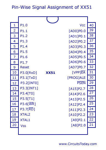
From the figure above, you may note that INTO is an alternate function P3.2 and INT1 is an alternate function of P3.3. A signal received at these pins will evoke the interrupts accordingly. But not all signals will evoke the interrupt! The signal received at pins should be either a low level one or it should be a falling edge signal to evoke the corresponding interrupt. However to serve the interrupt upon receiving the signal at pins, the man who programs 8051 should preprocess a few bits 3 SFR’s namely TCON, IE and IP. Let’s examine them.
TCON

TCON is a bit addressable SFR. Out of the 8 bits, only the lower 4 bits are concerned with external interrupts. The upper 4 bits deals with interrupts from Timers. The lower four bits are TCON.0 (IT0), TCON.1 (IE0), TCON.2 (IT1) and TCON.3 (IE1). You can refer the figure given below for a better understanding. Out of these 4 bits, bits 0 and 1 – that means – TCON.0 and TCON.1 are concerned with external interrupt 0 (INT0), where as bits 2 and 3 – TCON.2 and TCON.3 are concerned with external interrupt 1 (INT1). Out of these bits only TCON.0 and TCON.2 are directly manipulated by the programmer while dealing with an external interrupt. Bits TCON.1 (IE0) and TCON.3 (IE1) are manipulated by the processor itself. An external signal received at INTO would set the bit TCON.1 (also known as IE0) and will be cleared by the processor itself, after it branches to the corresponding ISR located at 0003H. Similarly TCON.3 is set when an interrupt signal is received at INT1 and would be cleared by processor after branching. The other 2 bits TCON.0 and TCON.2 are used for selecting “type of signal” received.
TCON.0 (or IT0) is set to 0 – if the interrupt at INT0 is to be evoked by a low level signal. If TCON.0 is set to high, then the interrupt at INT0 would be evoked by a falling edge signal (high to low transition). Same is the case with TCON.1 – if set to 0 then low level signal would raise an interrupt at INT1 and if set to high, then a falling edge signal would do the job.
IE (Interrupt Enable)

There are 3 bits associated with external interrupts in IE – they are bits 0,2 and 7. The main purpose of this SFR is to enable/disable different interrupts based on whether it’s corresponding bits are set or not. Refer the figure below.
IE.7 – is known as global interrupt bit – which when set to ‘0’ – disables all kinds of interrupts in 8051. Only if this bit is set to ‘1″, any kind of interrupt would be enabled in 8051. If this bit is set to 1, programmer can then individually enable or disable all other interrupts INT0, INT1, Timer interrupts (0 and 1) and serial interrupt.
IE.0 – If set to ‘1’ – it enables INT0 and if set to ‘0’ – INT0 would be disabled. So in order to enable external interrupt 0 (INT0) – IE.7 and IE.0 should be set to ‘1’.
IE.2 – Similar to IE.0 – IE.1 enables/disables external interrupt 1 (INT1).
Interrupt Priority (IP)

Basic function of this SFR is to set interrupt priority (IP). By default INT0 is of priority value 1 (which is the highest) and INT1 is of priority value 3 (which is lower than INT0). The programmer can alter this priority, if he wants! If IP.0 is set to ‘0’ and then IP.2 is set to ‘0’ – then the priority order changes. INT1 will change to high priority and INT0 will change to lower priority compared to INT1.
How to write an ISR (Interrupt Service Routine)
An ISR is just like any other subroutine we write inside a program, except for the difference that an ISR must always end with a RETI instruction and not with a RET instruction (as in the case of subroutines). An ISR when evoked, executes a certain lines of code that does some kind of operations. It can be anything as defined by the programmer. The only condition is that the first line of ISR must begin from the corresponding vector address. Vector address of INT0 is 0003H and that of INT1 is 0013H.
Note: In some cases the ISR will be too long that it wont be practical to write all codes staring from 0003H or the other vector address. In such cases, ISR can be placed at any other location in program memory and programmer must provide an unconditional jump to the starting address of ISR from the corresponding vector address. Example:- The ISR of INT0 has been written from location 2000H. Now programmer must place an instruction – ‘LJMP 2000H’ at the vector address of INT0 – 0003H.
Note:- Whenever an evoked interrupt is acknowledged and the processor branches to its corresponding vector address, it automatically disables the interrupt in IE register. This disabled interrupt would only be re-enabled upon executing the RETI instruction placed inside the ISR. That is the single reason, a programmer must use RETI inside an ISR instead of RET instruction. Placing RET will also do the job of returning from interrupt routine to main program (the calling program) but the RET instruction will not re-enable the disabled interrupt in IE register. So if an RET is used, the interrupt would be permanently disabled after its first serving of ISR (unless it is enabled again by the programmer at some other part of the same program).
So in order to write an ISR for INT0, you have to keep in mind the following things:-
1) Place the ISR for INT0 beginning from its vector address – 0003H. If the ISR is too long, place an unconditional jump from 0003H to the starting address of ISR (which is placed at some other location of program memory). The ISR must end with a RETI instruction.
2) Select the triggering signal type of interrupt by setting/clearing TCON.0 bit. TCON.0=1 – means interrupt would be triggered by a falling edge signal. TCON.0 =0 – means interrupt would be triggered by a low level signal.
3)Set IE.0 =1 to enable the external interrupt 0 (INT0)
4)Set IE.7=1 – to enable the global interrupt control bit.
5) Optionally, programmer can alter the priority of INT0 by setting/clearing IP.0 (Note: This step is optional.)
Now when it comes to external interrupt 1 – INT1 – the processes are all same, except for the change in bits that are to be programmed.
1) Place the ISR in vector address of INT1 – 0013H. Or if the ISR is long, place an LJMP at 0013H to the corresponding starting address of ISR for INT1.
2)Triggering signal type is selected by setting/clearing TCON.2. TCON.2 = 0 – triggered by low level signal. TCON.2 = 1 – triggered by falling edge signal.
3)Set IE.2 = 1 to enable INT1
4) Set IE.7 =1 to enable global interrupt control bit.
5) Interrupt priority can be altered by changing value of IP.2 (optional). Refer the diagram of IP register given above.
How to generate Software Interrupts in 8051?
Software interrupts are nothing but an interrupt generated by a program inside the controller. To generate an external interrupt, we need a signal input either at INT0 or INT1 pin of the 8051 micro controller. We have seen that, when an interrupt signal is received at the INTo pin, the TCON.1 bit would automatically get set and that is how the processor knows an interrupt signal has been received at INT0 pin. When TCON.1 is set, processor would immediately acknowledge the interrupt and branch to the corresponding ISR of INT0. While branching to the ISR, processor would also clear the TCON.1 bit. The same happens in the case of INT1 and the associated bit is TCON.3.
Now in order to generate a software interrupt, the programmer can manipulate these bits TCON.1 and TCON.3 manually inside a program. An instruction like ‘SETB TCON.1’ will activate the interrupt for INT0 (without any external signal at the INT0 pin) inside the controller. Now the processor will acknowledge the interrupt and branch to the corresponding location of ISR for INT0 (vector address 0003H). After branching to ISR, the processor would clear the bit TCON.1. An instruction like ‘SETB TCON.3‘ would activate the interrupt for INT1 and processor would branch to ISR of INT1 located at vector address 0013H. While branching it would automatically clear the bit TCON.3, so that the programmer can activate the interrupt again inside a loop or some other part of the program.
Example Program:-
Previously,we have developed a circuit to toggle two LED’s with a single push button switch – in 8051. It has been developed for educational purpose.
1) To learn how to interface LED’s to 8051
2) How to use push button switch to manipulate output status of LED’s
3) How to use interrupt and develop an ISR for 8051.
You can see the circuit and article here:- Toggling 2 LED’s using 8051 – Learn the use of External interrupts
Note: In the program of above example, you can learn how to write an ISR for 8051. INT0 is used in the program. Also note – how the program branches from vector address of INT0 – 0003H to some other location.
Any doubts/queries ? Comment here!
Note:- If you are interested in AVR, then here is a good article for you:- Handling external interrupts in AVR
10 Comments
Thanks a lot for the copy of the study material. this is exclusively for my study only and is not for any other purpose.
faithfully, T.K.Venkiteswaran.
Nice Post, Thank you very much
In the interrupt priority
px0 is clear int0 goes to lower priority its correctly explained by u.but
px1 is set only int1 goes to higher priority.
but u explained like if px1 is also clear then int1 goes to higher priority in explanation.in diagram its correct.so which is correct..explain me please
….
nice post over there but my my question is,which programming language is best suitable for writing the software
@dennis – You can either use assembly language or Embedded C.
@srihari and @rowan – Thank you for the nice words 🙂
thanks fantastic im buying some chips end of month then im gonna start where i left off
rowan
Nice post. 🙂