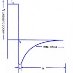
Turn-on and turn-off characteristics of an SCR are called the dynamic characteristics of the SCR.
(a) Turn-On Characteristic.
The turn-on time characteristic shows the variation of current and voltage during turn-on. Turn-on time is defined as the time from the initiation of triggering, when the SCR offers infinite impedance to the flow of anode current, to the time when an equilibrium charge distribution is established throughout the device together with a steady state forward voltage drop. The turn-on time is about 1 to 3 micro seconds for the SCR readily available commercially.
Figure shows the form of current rise during the transition from the non-conducting to the fully conducting state. The time tO indicate the initiation of turn-on which is caused by a step function of voltage applied to the gate. The period td is the delay time between the front of the gate pulse and the beginning of a rapid rate of increase of anode current. During the initial interval of turn-on (td) only a small area near the gate electrode conducts anode current. td is due to the charge build up time and decreases with the increase in gate current. The rise time, tr depends on the speed at which charges build up to support the final anode current, IA. tr is independent of gate current but depends upon the widths of base an construction of SCR. The sum of td and tc gives turn-on time ton. The turn-on time ion depends on the anode circuit parameters, gate current amplitude and rise time. The turn-on time is important in pulse triggering.
(b) Turn-off Characteristic.
Turn-off means that all forward conduction has ceased and the re-application of a positive voltage to the anode will not cause flow of current without there being a gate signal. The turn-off characteristic is shown in figure. The time t0 indicates the instant of application of reverse voltage, trr is the duration for which the reverse recovery current flows after application of reverse voltage and t is the time required for the recombination of all excess carriers in the inner two layers of the device. The sum of time duration trr and time duration t gives the turn-off time t0ff, that is t0ff = trr + tgr . At the end of turn-off time, a depletion layer gets developed across junction J2 and now SCR is capable of withstanding forward voltage. The turn-off time depends upon anode current, magnitude of reverse voltage and the rate of application of forward voltage.


10 Comments
Overall explanation is good but if explanation is given by using the waveforms it will be easy to understand