Description.
A very simple battery charger circuit having reverse polarity indication is shown here.The circuit is based on IC L200 . L200 is a five pin variable voltage voltage regulator IC.The charging circuit can be fed by the DC voltage from a bridge rectifier or center tapped rectifier.Here the IC L200 keeps the charging voltage constant.The charging current is controlled by the parallel combination of the resistors R2 & R3.The POT P1 can be used to adjust the charging current.This circuit is designed to charge a 12 V lead acid battery.The transistor t1,diode D3 and LED are used to make a battery reverse indicator.In case the battery is connected in reverse polarity ,the reverse polarity indicator red LED D5 glows.When the charging process is going on the battery charging indicator green LED D4 glows.
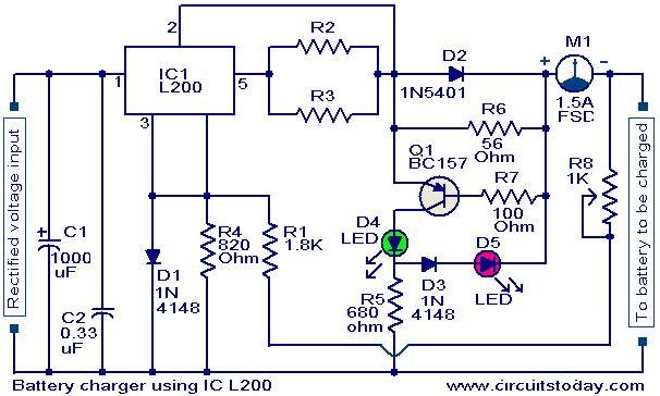
Circuit diagram with Parts list.
Notes.
- The circuit can be assembled on a good quality PCB or common board.
- The values of R2 & R3 can be obtained from the equation,
(R2//R3) =( V5-2)/(Io).
Where V5 is the charging voltage (voltage at pin 5) and Io is the charging current.
- The POT R8 can be used for fine adjustments of charging current.
- If battery is connected in reverse polarity the RED LED will glow.
- When the charging is going on the GREEN LED will glow.
- The rectified input voltage to the charger can be 18V.
37 Comments
How to cut off the current to prevent an overcurrent by using the L200, should be?
Hello sir,
I want to charge Ni-MH 9V/200mAh battery, can i use this circuit?
If ye, please guide me to add automatic cutoff after the completion of battery charging…
Your early reply will be very helpful to me.
No this is for la batteries only. For your NiMH you have to use a 20mA constant current source and charge for 15 hours.
i need battery charger of 12V,10A with over load control, reverse polarity and boost/float indication. please reply with specifications of material
I need acharger circuit charges 12 v /70ah car battery with over charge control or full charged indicator
can i use this circuit for my jump starter with a battery of 12 volts and 18ah ? please reply to my email ..thanks
how are value (R2, R3) in battery charging useing IC L200 diagram.
Hi
i want to make a battery charge controller.
i have 2 batteries of 3.5 Ah 12v.
Can this circuit is suitable for me for charge controller?
Sir,
My doubt is this circuit will work on 5 volt and o.5 amp battery range or not??please mail me sir.I really need this information.
Hi Sayak this charger is for Lead Acid Batteries of 12volts 10 to 12AH batteries only.
Hi sir, may i ask how much input voltage do i require to charge a 12V 1.2ah battery? and any modification i need to make in this circuit ?
It means when the battery is not charging, the red LED light will light up? and green will light up once there’s supply voltage to charge the battery?
hi sir. please does this circuit carry out trickle charging. if not i need a circuit for 12v 45Ah trickle charger.
hi, plz help me as m not getting the value of r2 and r3. Plz mail me and tell the correct value with circuit diagram.
Your notes are very useful to me. Thank you very Sir.
Hi Favour you require 15 volt 20Amps charger. you can use the following circuit with suitable pass transistors to increase current capacity to 20amps. do not forget to replace the transformer with 20 amps capacity.
pl. I want to build a battery charger rated 12v,75AH.help me with circuit
I want to ask the reason of using 1.5A FSD component used in the above schematics and its little bit introduction. Can u plz mail me the details.
I would like to resurrect an old charge car batteries and provide it with a new charging circuit.
I wanted to know if at this circuit you can add a few transistors (eg 2N3055) to increase the charge current.
I wanted to know if the battery is charged when the circuit stops charging.
I would use the existing transformers, I added a bridge rectifier diode and a capacitor 6.8 mF and I measured in the output 21VCC
If someone is kind enough to send me some simple automatic battery charger and stabilized.
Greetings
Thanks
Hi Paul the limitation for L200 is 2amps. you can use any PNP power transistor similar to, increasing current capability of 3pin regulators. please refer to national application
http://www.national.com/an/AN/AN-103.pdf
I would like to resurrect an old charge car batteries and provide it with a new charging circuit.
I wanted to know if at this circuit you can add a few transistors (eg 2N3055) to increase the charge current.
I wanted to know if the battery is charged when the circuit stops charging.
If you have any simple battery charging circuit stabilized and can automatically send it to me
Greetings
Thanks
45amp charger circuit diagram
Hi Hillary there is no direct equivalent. you can use LM338 for voltage regulation, with external current limiting circuit. You can refer to the following circuit.
https://www.circuitstoday.com/24v-lead-acid-battery-charger-circuit
Iam a student, what is the alternative IC to L200 IC.
Hi Vijay the following circuit will be best suited for you it can charge up to 150AH battery.
http://powersupply.circuitelectronic.net/13-8v-40a-high-current-power-supply/
Hi
I want to build a lead acid battery charging circuit for the 100 AH lead acid battery. this means battery charging current should be 1/10 = 10 amps. 15 amps current rated battry charger circui i needed. kindly send the circuit diagram for the same. to my email addresse gaikwad.vs@rediffmail.com.
thanks in advance.
Regards.
Gaikwad Vijay
Hi Holly V5 and Io depends on the battery you want to charge. it depends on its terminal voltage and AH capacity. R2 & R3 are in parallel enable you to make the required value by using standard preferred values.
Hi
What are the Ohm(s) and watt(s) of R2 and R3, and define the formula using the correct values of R2 and R3 including V5 and Io.
HollySmoker
aquarious_16@hotmail.com
Hi Asad give your comment in english so that every one can understand you.
me v ik student aan menu v a website changi lgdi a pla hove.
hi
just asking about the circuit above using ic L200. what are the values of R2, R3 and what are the size of all resistors in terms of watts?
thanks and hope you reply asap…
jbs
Values of R2 and R3 can be obtained from the equation
(R2//R3) =( V5-2)/(Io)
Where V5 is the charging voltage (voltage at pin 5) and Io is the charging current.
They can be 1/2 watt resistors
dude the output current is very low.its around 200 ma.i used 18 volt 2amp transformer with regulator of 18 volt.any solution for that.i want at least .5 amp of current.plz reply.
Hi,
one more quest..
M not good in Maths.
What would b value of R3 & R2 if I have a 12V SLA & I want to charge it with 700MA.
Please help.
Tamseel.
Hi, In this above Circuit, wat is M1?
I believe it is an Ameter, but is it neccesary to connect it or I can short the same?
Tamseel..
i am a studen and this web is so best learn for me
thanks