Description.
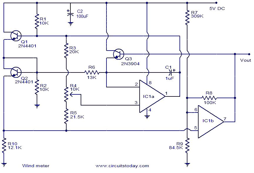
Here is a very simple wind meter (anemometer) circuit. I can’t guarantee much on the accuracy of this circuit but it circuit works quite fine. You can measure wind speeds up to 75m/s using this circuit.
The transistors Q1 and Q2 are used for sensing the wind. The relationship between thermal impedance of the transistor and the surrounding wind speed is utilized here. Transistors Q1 and Q2 are wired so that the Vce of Q1 is higher than Q2 and therefore there will be a higher power dissipation. The wind causes cooling and so the Vce of Q1 changes. The ends in different power dissipations and different voltages across R10.This variation is detected by the opamp and amplified to produce the Vout which is proportional to the wind speed. For still air Vout will be 0V and at 75m/s wind speed the Vout will be 2.5V. A 3V FSD voltmeter connected across the Vout terminal and ground can be used as the display.
Circuit diagram with Parts list.
Notes.
- The circuit can be assembled on a Vero board.
- The circuit can be powered from 5V DC.
- For proper working, the air must pass over both the transistors (Q1 and Q2).
- Most of the resistors used here are not standard values. So you need to use the combination (series or parallel) of resistors to attain the specified values. Please note that the resistor values are very critical in this circuit.
- IC1 is an LT1013 dual opamp.


6 Comments
I tried making thus circuit.Its not working pls give some idea transistor is not getting cooled or heated.what we can use in place of transistor for this same circuit & What can be added here to improve accuracy & output range reply soon I need to make this project asap.
nice idea