If you are looking for a Water level indicator or a Water level controller, there are pretty good circuits we have developed. This one is just a fun project made for hobby purpose! You can call this a water sensor circuit for sure!
Description.
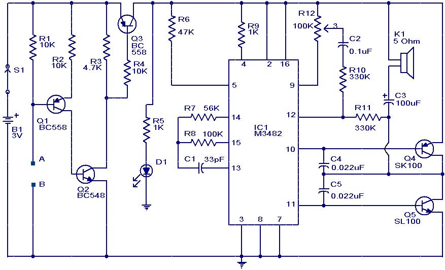
This is a simple musical alarm circuit which produces a musical tone when water or some conducting liquid comes in contact with the two sensor wires provided. The circuit is based on four transistors and one melody generator IC (M 3482).
When water comes in contact with the sensors wires A & B, the base of Q1 gets connected with the negative and it conducts. This makes Q2 and Q3 ON. When Q3 is ON the power is available for the music generator circuit and it starts producing 12 different melodies one after another. The music continues as long as there is water between the sensor wires. The POT R12 can be used as a volume controller.
Circuit diagram with Parts list.

Notes.
- Assemble the circuit on a good quality PCB or common board.
- Two insulated aluminum wires can be used as the sensor.
- The IC1 must be mounted on an IC holder.
- The speaker can be a 8 Ohm, ½ W tweeter.

17 Comments
Is there replacement for IC m3482?? Pls reply . Master
hello seetharaman..nice work…can u tell me if i can use this circuit in water pipes for determining liquid flow using aluminium probles??Also the distance of probes is at least 3 meters..
how the music will come from speaker ;????
whether the music is internally stored in Ic r what? ????? please reply
YES…….music is internally stored
Hi,
i am Mohsin, I need a circuit which detects motion of liquid in an iron pipe from outside, I mean I may be able to know when water passes through the metalic pipe. Please help
Thanks
Hi Mohsin there are surface mounted ultrasonic water liquid flow meters are available for this application. The following site will give you more details.
http://www.omega.com/prodinfo/ultrasonicflowmeters.html
what are the other water sensors rather than using aluminium wire???
Hi Ahmed you can use stainless steel wire or thin ss rod, which will be the best sensor and can be cleaned once in three months if you are using DC. if ac supply is used for sensing nothing will happen to the sensors at all, no cleaning is also required.
can you help me with my circuit. Motor with Sensor circuit .
Circuit
Hey,this is shrikant. I am doing this topic as my mini project for third year EXTC engg. I am curious about this topic n just wanted to know whether this circuit will work properly or not….also please tell me if there are any changes to be made in this diagram…please reply ASAP…
This is a basically melody generator chip switched on when the probe touchec water. Q1 Q2 and Q3 are the sensing cum switching circuit for feeding DC supply to melody IC 3482. This is a quite reliable circuit you can proceed.
Hi Bitrus you can try the other sounding circuits (Music ROM chip)in place of IC 3482 between collector of Q3 and common negative line.
this circuit is very helpful in project
is there replacement for m3482
Hi Darshana SL100 can be replaced with BL100N, CL100, 2N1711, 2N2219, 8050, BC337 BD136
are there ay replacement for SL 100 ?