Description.
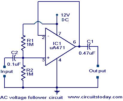
An AC coupled unity gain gain voltage follower operating on a single supply is shown here.The voltage divider network of R1 and R2 provides a DC voltage equal to half the supply voltage to the non-inverting input of the 741.The output DC voltage therefore stands at half the supply voltage.The output signal swings above and below this value.The standing DC voltage at pin 6 does not matter because the output is coupled to the next stage via a capacitor.
The input impedance is equal to the value of R1 and R2 in parallel, i.e .500K Ohms in this case.Because of hundred percent negative feedback ,the output impedance is very low.For low frequency applications C1 and C2 can be replaced by electrolytic capacitors of large values.
Circuit diagram with Parts list.
Notes.
- Assemble the circuit diagram on a good quality PCB or common board.
- Power the circuit from a 12V battery or 12V DC power supply.
- The IC 741 has to be mounted on an IC holder.
3 Comments
Like to know about the circuit physically
Nice explanation and awesome layout> I have already saved your site in my favorites 🙂
Dear Sir,
I need a buffer circuit for measuring a 10V sinusoidal DC voltage with a very low current.(0.01 mA)
Could you please help me?
Thanks,
Shilati.