In this chapter, let’s learn how to use the Virtual COM Ports in Proteus software. Virtual ports offer an option to connect the external hardware to the simulation software. The designer can interface any of the UART based modules through the virtual ports in Proteus software.
Nowadays, various sensor modules like GSM, GPS, RTC (real time clock) communicate through the UART Communication Protocol. Such modules can be interfaced with the virtual ports in Proteus. Also, these modules can communicate with the microcontrollers inside the simulation software. This eliminates the requirement of hardware components for testing your circuit idea. So, the designer can first test the circuit & implement the embedded program with the help of Proteus software and if the results are satisfactory, it can be implemented using proper hardware components.
UART Based Modules
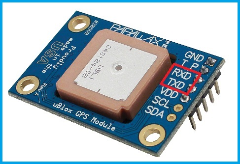
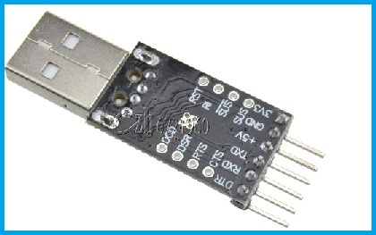
This is basically a serial port, with RS-232 Protocol. A level conversion IC like MAX 232 should be used to connect with the microcontrollers. But, if the serial port is not available on your computer, USB to serial converters are available. The output of this converter is 5 Volts or 3.3Volts TTL Logic. This output can be connected to microcontrollers directly. A Suitable device driver should be installed.
USB to Serial converter
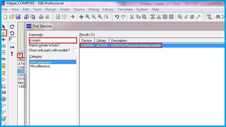
Using Virtual COM PORT in Proteus
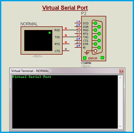
Com Port is under Active library of components. It is described as Physical Interface Model-PIM. For serial communication, the RX and TX pins are sufficient. But for actual RS 232 protocol communication remaining terminals are also used.
A Virtual terminal is used to send and receive the data through the port. Data can be sent through the keyboard and received data is displayed on the virtual terminal.
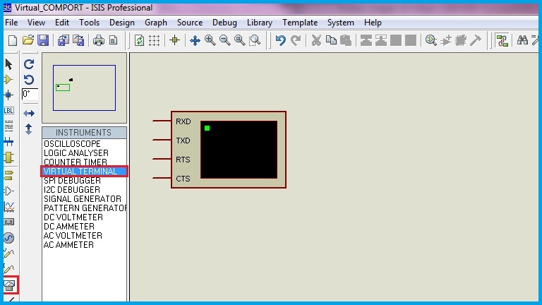
This virtual terminal is like the circuit behind the connector. So, the RX and TX pins of both are connected one-to-one directly.
Now, we have to set the properties for the desired operation. Physical Port number and communication rate are the essential parameters to be set. Remaining parameters are generally common for most of the applications. Properties of the virtual terminal also should be set similar to the COM Port.
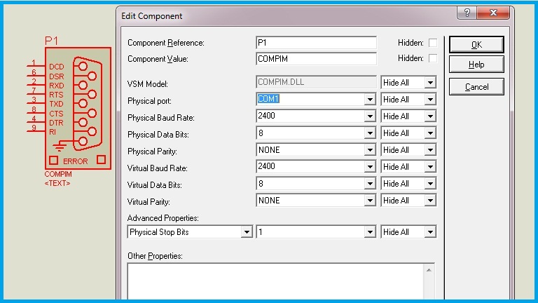
These parameters should match with the external module that we are interfacing. So, it is better to study the data sheet of the interfacing module, for its default baud rate and other parameters and then set them in the software. Similarly, these properties should match with the Virtual terminal.
Interfacing UART Module using COM Port
In this example, a GSM Module is used. Any module with UART pins can be used. The basic command of UART Modules is the attention command i.e., AT Commands. We have to write AT and press the enter key in the virtual terminal. This data is transferred through the Selected COM port and data sent by the module is shown in the virtual terminal.
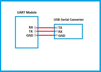
The above image shows the connection of a GSM Module and the USB to serial converter. The USB-Serial converter will be shown in the devices and printers as USB-Serial comm port. The actual Port number also will be shown.
Screen Recording – Interfacing UART Module using COM Port
Interfacing UART Module with a virtual microcontroller
It is possible to interface the external module with a microcontroller inside the Proteus software i.e., to interface virtually. It is like Microcontroller inside and Module outside.
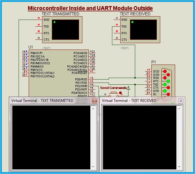
This feature is useful to the designer during the development of the application firmware. If the selected microcontroller is sufficient and gives the desired result, then it can be implemented on hardware. Otherwise, the program can be modified or another microcontroller can be selected and tested.
Simulation – UART Module With A Virtual Microcontroller
Thus we finished our tutorial on How to use Virtual COM port in Proteus. I hope you have clearly grasped the concepts of UART Modules and communication.
3 Comments
To view the text typed on the virtual terminal during simulation
Right-click on the Pop-up terminal during simulation and select “Echo typed characters”.
i simulate everything just fine and the virtual terminal pops upm but wont allow to type anything