Description.
Here is the circuit diagram of a versatile FM transmitter that doesn’t have a coil. The circuit is simple and easy to assemble.
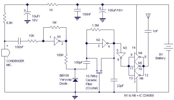
The gate N1 acts as a buffer for strengthening the signals from the condenser microphone. The inverter N2 with its associated components forms a radio frequency oscillator in the FM region.The varicap diode BB109 is used for frequency modulating the audio signal to the carrier wave generated by the oscillator.Inverters N4 t0 N6 are used to drive the antenna.As the N4,N5,N6 are connected in parallel their effective output impedance is very less and can easily drive the antenna.
Circuit diagram with Parts list.
Notes.
- All electrolytic capacitors must be rated 10V.
- Use any general purpose condenser microphone.You can easily get one from old telephone or tape recorder.
- Use a 10 cm long wire as antenna.
- Gates N1 to N6 belong to same IC CD4069.
- The battery can be a 9V transistor radio battery.Adapters are not recommended because they would induce noise in the circuit.
19 Comments
dear sir… how many dictunce do this circuit ?????
pls answer to my mail….
i want this one
plz
Hi Sir,
I made this circuit. All connections are correct on veroboard.
But this is not working properly.I unable to find RF frequency in FM receiver.
* BB109 is not available.I use “910 AT” from a fm receiver.
* How can I change tuning frequency in tx.
* If desire frequency is not in 88-108MHz,what can I do then to maintain this frequency in 88-108MHz.
* Which anteena is better to transmit RF.
* How many distance should kept between Tx and Rx.
Please kindly help me.
Hi Sir,
I made this circuit. All connections are correct on veroboard.
But this is not working properly.I unable to find RF frequency in FM receiver.
* BB109 is not available.I use “910 AT” from a fm receiver.
* How can I change tuning frequency in tx.
* If desire frequency is not in 88-108MHz,what can I do then to maintain this frequency in 88-108MHz.
* Which anteena is better to transmit RF.
* How many distance should kept between Tx and Rx.
Please kindly help me
Hi Tutu Zulu BB109 is a varactor diode (commercially varicap diode- variable capacitance diode). You can use BB105 the common one.
Sir, what is the equivalent for BB109?
Hi Sir,
I made this circuit. All connections are correct on veroboard.
But this is not working properly.I unable to find RF frequency in FM receiver.
* BB109 is not available.I use “910 AT” from a fm receiver.
* How can I change tuning frequency in tx.
* If desire frequency is not in 88-108MHz,what can I do then to maintain this frequency in 88-108MHz.
* Which anteena is better to transmit RF.
* How many distance should kept between Tx and Rx.
Please kindly help me.
Hi Saad a telescopic whip antenna from a old MW / SW portable transistor set, extended to around 70cms in length.
In the higher end of my analog FM 2 in 1, say aroung 107MHz.
You can use PP3 but alkaline.
capacitor without positive and negative terminal is called non polar capacitors normally used in loud speaker cross over networks.
at present i donot have any micro wave projects.
hi sir.
1)what length of antenna wire did u used in u r own design and at what frequency did u received the voice?
2)insulated copper wire antenna?
3)will 9Vpp3 battery can be used?
4)tell me about the name of capacitors without positive and negative terminals?
thanks.plz answer all my queries?plz.
can u guide my about any microwave related projects?
waiting for u r response?
Hi Neelam Kindly go through the discussion
http://www.edaboard.com/ftopic376629.html
there is a formula to find distance between Tx’r and Rx’r called Friss formula…..
Hi Neelam I have made a prototype and used a wave length / 4 whip for 10th hormonic and got the signal on my FM portable receiver and practical check was done and it was found to be reacheable upto 100feet (without any obstruction on an open terrace). If you have got a full-fledged set up you can measure the power transmitted and with field strngth meter you can plot etc. These are all simple circuits for fun! not a very serious design a small novel idea.
how did you find harmonic and distance is there any formula..plz let me know….
thank you Seetharaman,
as i didnt know the range…i had given “Sine wave of 10 KHz” as an input and observed output on spectrum analyser .it gives output but the biggest problem is it shows “peak” of carrier at 80 MHz.which is out of range…it also shows sidebands on 100 and 60 MHz…..so what i should do to boost frequency ????
Hi Neelam the following site will give you the details. In my openion the 10th harmonic say 107 MHz will be the transmitting frequency ( our FM broadcast band is from 88 to 108MHz). You may use a λ / 4 whip antenna 70cms in length. If an inverter’s output is fed back its output will get stabilised at 50% of the supply voltage (negative feed back)hence it will become an inverting analog amplifier. BB109 and MV109 is same can be used. It is similar to a single transistor crystal oscillator, using 10.7MHz crystal filter.
The distance can be around 50 to 100 feet
http://www.electronic-circuits-diagrams.com/radioimages/radiockt8.shtml
1.at what distance receiver should be??
2.what is frequency of receiption??
3.how inverter acts as amplifier and oscillator??
4.what is the formula to find carrier frequency??
5.BB109 is not available in market..can I use MV209(5-22pf)
please answer as many as you can.n as soon as u can…help out please
what is the frequency how can i change it
What is the frequency it transmit ?
How can I change it ?
thanks
ok