UART Between Microcontrollers Using Proteus
UART stands for Universal Asynchronous Reception and Transmission of data serially between two terminals. This mode of communication has the advantage of data transmission using lesser number of I/O Pins. For longer transmission distances this is essential as it involves less number of transmission wires. In this article, we shall see how two microcontrollers communicate with each other using their UART peripheral.
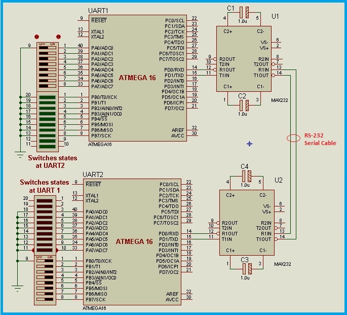
UART Bridge Between Two Microcontrollers
We shall discuss this through a simulation project involving switches and LED’s. This example project updates the status of switches connected to the microcontroller to the opposite microcontroller through the UART Communication. The logic is developed such that, whenever there is a change in the state of the switches, the present state of the switches is sent to the opposite controller. Thus, the present state of switches connected to ‘UART1’ is shown by the ‘UART2’ and vice versa. The input ports of the microcontroller are internally pulled-up. So, the ON State of the switch indicates Low input and OFF State of the switch indicates High input to the microcontroller.
RS-232 Standard for Serial Transmission
The circuit discussed in the UART Bridge example is suitable for the On-Board microcontrollers i.e., when the two microcontrollers are on the same board or nearer to each other, generally up to 6-Inches apart with a good PCB layout. In case if the microcontroller is at remote location, then the signal has to be strengthened and transmitted. For this purpose, the voltage level of the signal is increased.
In addition to the RX and TX pins along with the Ground/Common terminal, the RS-232 Protocol contains some other signals for establishing communication. These pins are used for data flow control. These pins are individually controlled by the microcontroller for proper and valid communication and to avoid loss of data. These pins are,
- CTS – Clear To Send
- RTS – Request To Send
- DCD – Data Carrier Detect
- DTR – Data Terminal Ready
- RI – Ring Indicator
- DSR – Data Set Ready
It is not mandatory to use the flow control pins. These pins do not have direct control over the UART registers. These pins are read or written by microcontroller as I/O pins.
Real-Time Application Idea for RS-232
Suppose there is an auditorium with limited occupancy and there are two counters to issue the tickets. These counters are considerably far away such that topics like the number of tickets left cannot be communicated easily and usage of preprinted tickets is not possible. In such cases, the following circuit can be used. It is just an example to demonstrate the concept.
The program flow is in such a way that, each time when a ticket is issued at one counter the remaining tickets are updated at both the counters so that, the issuing person has the knowledge of how many tickets can be issued further. As the counters are remotely located, the RS-232 mode is used to connect these two counters.
The flow chart for the above example is shown at the end of the article. In order to execute the flow chart, we need to know how to use the UART Peripheral of a microcontroller. Let’s discuss how the UART Mode of a microcontroller is used, by discussing various parameters of the communication protocol.
Voltage Level
UART Protocol is one of the Serial data transmission modes. The voltage level of UART is either 5V-TTL or 3.3V. This voltage level is suitable for On-Board data processing between two terminals on a single PCB or with in a small control panel. But, for long distance communication, the voltage level is changed. Mostly this voltage level is altered to RS-232 Standards using a level shifter IC like ‘MAX 232’. This level shifting IC is by the UART Terminal to convert the TX (transmitting) Data to RS-232 Level and RX (received) Data to TTL Level. RS-232 communication standard cables are available. Based on the capacitance of the cables the transmission distance will vary. Cables up to 15Mts and above are available. If special cables with low capacitance are used, the distance can be increased further.
Data Frame
The data to be sent is framed into a particular format by the UART Terminal and pushed out from the TX pin. Before using the UART Mode, it is essential to define this format. The number of bits in the data frame varies with respect to the format settings. The various parameters of the frame are as follows
- Baud rate – Speed of data transmission
- number of data bits – Varies between 5-Bits to 9-Bits
- type of parity-Even or Odd or No parity
- number of stop bits – 1 Stop bit or 2 Stop bits
The below image is the timing diagram of the signal for an 8-Bit data, no parity and one stop bit type of data frame.
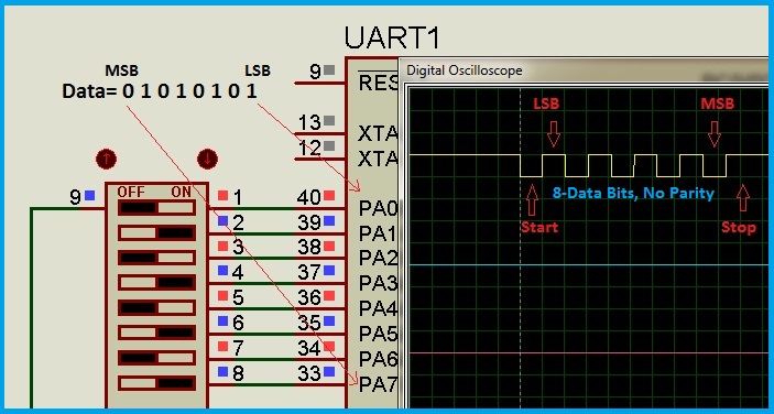
These settings should match between the two terminals, i.e., both the terminals should be defined with same parameters. The same format is applicable to the data received by the RX pin.
UART Registers
The data frame formats are defined using the UART Registers. There is a data register and it holds the data to be sent and the received data. These registers are named differently by different manufacturers, but the actual format of the data is similar. Let’s see the registers of ATMEL microcontrollers, particularly ‘ATMEGA 16’, the microcontroller used in above the example. It has four control registers and one data register.
- UCSRA – USART Control and Status Register A
This register contains the flag bits for various USART Operations which describe the status of the communication.
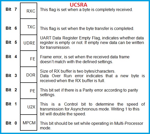
The flags that are mentioned in the UCSRA Register indicate various states of the communication. Let’s see them practically by intentionally generating errors to set the flags. For this purpose, UCSRA Register is read after every operation. The 8-Bits of the register are shown by the 8-Pins of an I/O port of the microcontroller.
DOR Flag: It is set if a new data byte is received while there are two unread bytes in the buffers. In the below simulation example, every switching operation in the circuit will transfer data to the opposite microcontroller. Let’s not read the received data. So that, after three switching operations, the DOR Bit which is the pin ‘PC3’ will be set.
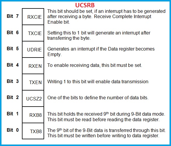
- UCSRB – USART Control and Status Register B
This register contains the Interrupt enable bits for the previously mentioned flag bits. Global interrupt register bit must be enabled for activation of any of the interrupt. Receiving and Transmission enable bits are also defined in this register.
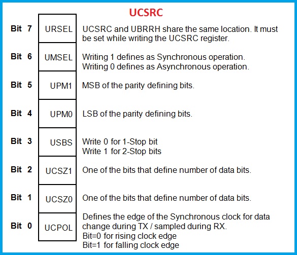
- UCSRC – USART Control and Status Register C
This register contains the Synchronous/asynchronous mode selection, Parity defining bits, number of stop bits, number of data bits, clock edge selection.
Parity Defining Values:
| UPM1 | UPM0 | Parity |
|---|---|---|
| 0 | 0 | Disabled |
| 0 | 1 | Reserved |
| 1 | 0 | Even Parity, Enabled |
| 1 | 1 | Odd Parity, Enabled |
The receiver will generate a parity value after receiving every data byte and compares with the parity settings. If there is a mismatch between generated value and defined value, Parity Error flag in the UCSRA Register is set. So, if parity is enabled, the software has to verify this flag before using the received data byte.
Data Bits Defining Values:
| UCSZ2 | UCSZ1 | UCSZ0 | No. of data bits |
|---|---|---|---|
| 0 | 0 | 0 | 5 Bits |
| 0 | 0 | 1 | 6 Bits |
| 0 | 1 | 0 | 7 Bits |
| 0 | 1 | 1 | 8 Bits |
| Reserved | Reserved | Reserved | Reserved |
| 1 | 1 | 1 | 9 Bits |
- UBRR – USART Baud Rate Register
The baud rate of the transmission is defined through this register. It holds a 12-Bit value. It has two registers UBRRH (Upper most 4-bits) and UBRRL (Lower most 8-bits). The particular value that must be written to this register for the desired baud rate depends on the CPU Clock frequency. UBRRH must be written before writing UBRRL. This value must be changed only during the idle state. Otherwise, the ongoing transmission will be disturbed. The value for 9600 baud rate at 16MHz oscillator with U2X=0 is ‘103’, a decimal value. Data sheets contain values for all the possible baud rates.
- UDR – USART Data Register
The data byte which should be transmitted is loaded or which is received is read through this register. The transmitter is single buffered, whereas, the receiver is double buffered i.e., it can hold two bytes of recently received data. If the start condition of an incoming byte is received while the two buffers are unread, the DOR Flag is set in the UCSRA Register. Data from the buffers is transferred to the UDR.
By now, we have the knowledge of using the UART Mode. Now, let’s recall our Ticket Issue counter example and develop the program code.
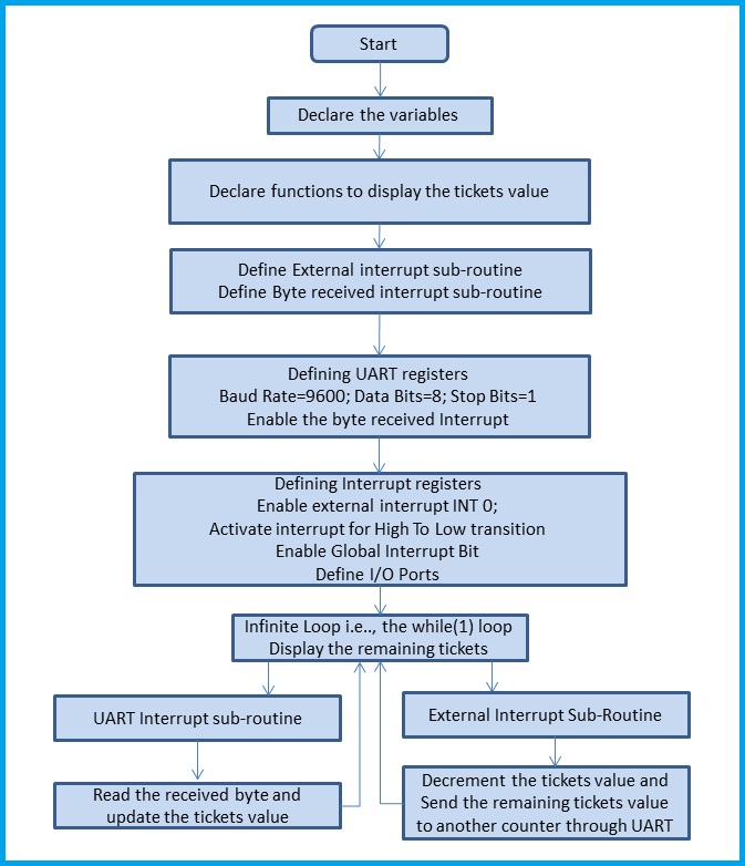
The above flow chart is put into a C-Program.
Download
The above flow chart is put into a C-Program. You can download the program here.
Comments are closed.