Applications of Triac
Next to SCR, the triac is the most widely used member of the thyristor family. In fact, in many of control applications, it has replaced SCR by virtue of its bidirectional conductivity. Motor speed regulation, temperature control, illumination control, liquid level control, phase control circuits, power switches etc. are some of its main applications.
However, the triac is less versatile than the SCR when turn-off is considered. Because the triac can conduct in either direction, forced commutation by reverse-biasing cannot be employed. So turn-off is either by current starvation, which is usually impracticable, or else by ac line commutation. There are two limitations enforced on the use of triac at present state of commercially available devices (200 A and 1,000 PRV). The first is the frequency handling capability produced by the limiting dv/dt at which the triac remains blocking when no gate signal is applied. This dv/dt value is about 20 Vmicros-1 compared with a general figure of 200 Vmicro s-1 for the SCR, so that the limitation of frequency is at the power level of 50 Hz. The same dv/dt limitation means the load to be controlled is preferably a resistive one. When high frequencies and high dv/dt are involved then the back-to-back SCRs cannot be replaced by the triac.

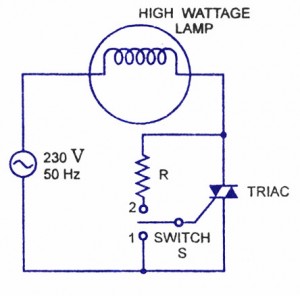
1. High Power Lamp Switching.
Use of the triac as an ac on/off switch is shown in figure. When the switch S is in position 1, the triac is cut-off and so the lamp-is’dark. When the switch is put in position 2, a small gate current flowing through the gate turns the triac on and so the lamp is switched on to give rated output.

2. AC Power Control.
A triac control circuit is shown in figure. Here it is controlling ac power to load by switching on and off during the positive and negative half cycles of the input sinusoidal signal.
During the positive half cycle of the input voltage, diode D1 is forward biased, D2 is reverse-biased, and the gate terminal is positive with respect to A1 During the negative half cycle, the diode D2 is forward biased and diode D1 is reverse-biased, so that the gate becomes positive with respect to terminal A2– The point of commencement of conduction is controlled by adjusting the resistance R2.

5 Comments
Its super an useful website thank u
I am a hobbyist of electronics, I am looking for
240A/120V Ac at 2Amp step down circuits using
Buck regulators.
Any how I am very glad to experience with this site.
Very much thank full
p.c.Rao.S
I would be interested in component ratings for the schematic in “2. AC Power Control.” or a link to calculations or reference data. I’d like to control 1500 – 2000 watts @ 120 volts.