Proteus software contains a large number of almost all types of transistors. This software can be used as a Transistor selector in circuits designing. This chapter on Proteus explains the basic circuits using transistors and analyzing those circuits with the tools available in the software.
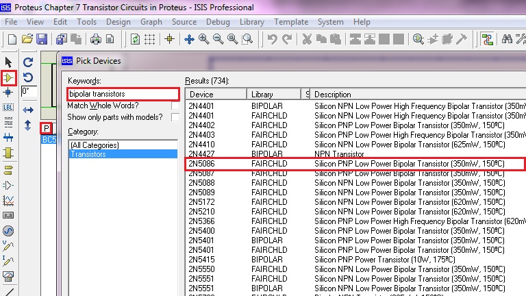
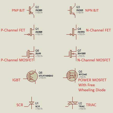
Different types of transistors like BJT, FET, MOSFET and some power electronic semiconductor switches like SCR, TRIAC, IGBT etc. are available in Proteus. Mostly BJTs are used for low power and amplifier applications, while MOSFET, IGBT are used for High switching frequency and High power rating loads; for example inverters, Home UPS etc. Even though SCR, TRIAC do not fall directly under transistor category, they are also similar to transistors in AC circuits.
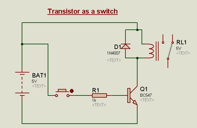
Transistor as a Switch
The basic application of a transistor is operating it as a switch. One of the most common use is to drive a relay to switch ON/OFF a load. The control signal may be obtained by manual input or may be generated by another block in the circuit.
This example explains, how to use a transistor as a switch in Proteus software, to operate a relay using the transistor BC 547.
The below video shows, how to lay the circuit in the workspace and basic operation of the circuit.
A transistor in switching applications has a Cut-Off mode and saturated mode operation. If the base signal is not applied, the transistor remains in OFF state known as the Cut-Off state. When sufficient Vbe is applied, the transistor turns ON and is in the saturated state. The typical operating conditions for different modes of a particular transistor are obtained from its datasheet.
As mentioned before, Proteus software can be used to analyze the circuits. The below video shows how to analyze a transistor circuit.
Bi-stable latching circuit using transistors
A bi-stable circuit has two stable states, i.e. the output terminal that is taken as reference remains either in the High or Low state depending on the switch position.
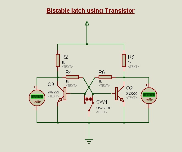
The state of the transistors is changed by changing the switch position. Between two switching actions, the transistors remain in one of their stable states. Below video explains the operation of the circuit.
Monostable circuit using transistors
A Monostable circuit has only one stable state, i.e. the output terminal that is taken as reference remains either in the High or Low state for a pre-set time duration.
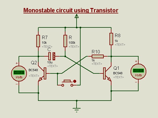
By applying negative edge to the output transistor, it changes its state from Low to High and remains in the high state up to a time constant duration T and gets back to low state i.e. the stable state.
T=0.693*R*C
Initially Q2 will be in the OFF state and the capacitor gets charged up to Vcc. When Positive pulse is applied, Q2 will turn ON and Q1 will turn OFF. Capacitor discharges through Q2. After complete discharging of Capacitor, Q2 will turn OFF and charges through Q1 making it turn ON.
Astable multivibrator
The astable circuit has no stable state, i.e. the output state toggles continuously with pre-set time period. This circuit is also called as a free running oscillator. This is used in square wave inverter circuits, running light circuits etc.
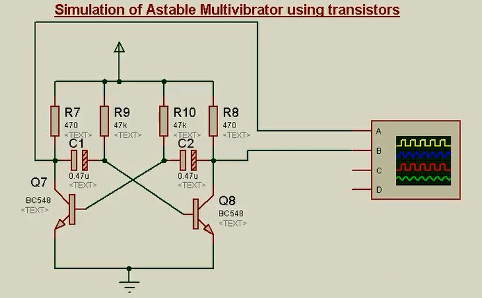
The charging and discharging cycles as in the monostable circuit, happen continuously in this circuit thus making it a free running oscillator. The time period is obtained from,
T=0.693*R*C
Square wave Inverter circuit
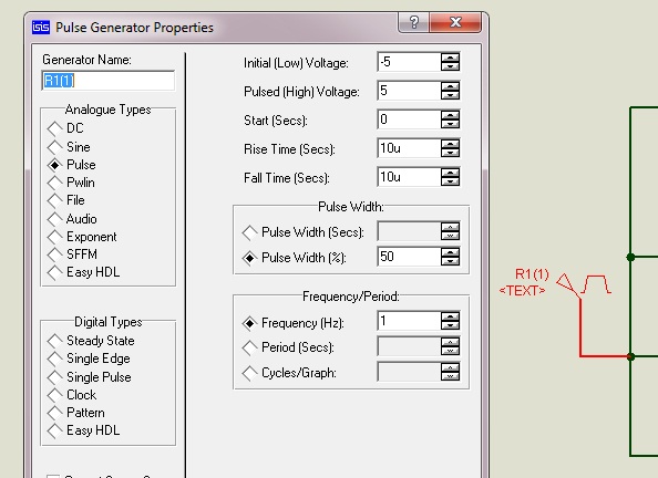
By using power transistors, square wave inverter can be designed. The circuit below uses pulse generator in the software to provide switching signals to the transistors.
The inverter circuit basically is a Push-Pull amplifier. When the switching signal is +ve sat, NPN transistor is turned ON and PNP transistor is turned OFF. Likewise, when the switching signal is -ve sat, PNP transistor is turned ON and NPN transistor is turned OFF. This makes the current to flow in both directions through the load.
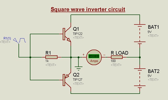
A transformer and a suitable capacitor may be connected (at secondary) to step-up the load voltage. However, this example concentrates on using transistors in Proteus software.
Comments are closed.