Description.
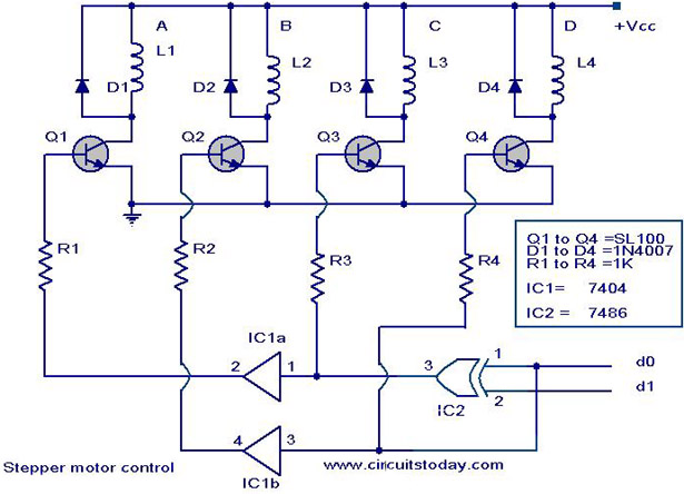
Here is the circuit diagram of a simple stepper motor controller using only elementary parts. The driver circuit uses, four transistor (SL100) to drive the motor windings, two NOT gates and one XOR gate to decode the two bit control logic to drive the four windings of the motor. The diodes D1 to D4 protects the corresponding transistors from transients generated during the switching of motor windings. d0 and d1 are the control logics which determines the direction of rotation as well as speed.
Circuit diagram with Parts list.
Notes.
- The control logic for the circuit can be obtained from a 2 bit up/down counter clocked by a 555 astable multivibrator.The direction of count determines the direction of rotation and the frequency of astable multivibrator determines the speed of rotation.
- As shown in the schematic above, IC1a IC1b belongs to same IC 7404.
- Pin 14 and pin 7 of both IC1 and IC2 must be connected to +5 V and ground respectively, though it is not shown in circuit diagram.
- The 5V can be obtained from a 7805 based power supply circuit.
- 5V power supply using IC 7805.Click Here.
- Vcc is the voltage required for the stepper motor. It varies from motor to motor. Here we can use up to 24V stepper motors. For higher operating voltages and power the SL100 transistors must be replaced with higher power transistors like 2N3055.
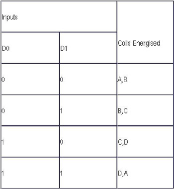
Truth table for clockwise rotation.
24 Comments
Dear Sir,
I have one 5-phase oriental Stepper motor (PK596BW-N25) which is attached to the drilling machine .Currently this motor speed is controlled by computer program but for some practical reasons I need to control its speed manually by knobs or button . Is it possible ? Do you have any equipment for that.
Thanks & Regards
Sameer A Kharadkar
in this circut,how can i stop the stepper motor from an input signal ?
Dear Sir/ Madam ,
Please let me know –
1. whether we can use this stepper motor control circuit
as a normal drive ?
2. with Break – Out board along with PC & Mach 3 controller???
3. up to 5 Amp. load what change required ?
4. After assembly it should required programming ?
if yes than how to programe ?
5. I REQURED CIRCUIT DIAGRAME FOR LPT / USB -BREAK-OUT BOARD WITH 4 NOS STEPPER MOTOR CONTROLLER .
please help Me .
Regards.
MANIK SHARMA
i need ‘how 8086 microprocessor control the speed of thee speed of DC MOTOR?
Hello
I’m not really familiar with stepper motors and drivers. Im doing research and im trying to understand the difference beteen a stepper motor driver , and stepper motor controller or as they the same thing. or is the controller the micro controller. im trying to hook up a driver to a dragon 12 board (micrcontroller) and use thatb to control the motor. how ever im trying to build my own driver so can someone please help.
Hey I am used this Circuit in My Project “FPGA Based Stepper motor Control”
Instead of Using IC’s of 2 Not GATE and Ex-or Gate , I have to program them Using VHDL programming.
Also Counter is to be Programmed and the Counter O/P is given to Not gate and EXor gate Circuitry.
Can you provide me the VHDL code for the 2 Bit Counter and the Counter O/P is given to Not gate and EXor gate Circuitry.
Need help in Vhdl Code
Hi, I’m working with this circuit, but unfortunately I can’t find SL100 transistors, stores down here in Mexico don’t have them in stock. Is it possible to use a ULN2803 instead?. Thanks in advance for your reply
Dear Sir
With the photocell signal why the its not work.
This is bag making machine unprinted with length
cut properly, but printed bag photocell signal
not operate. Please brief it.
Thanks for the simple circuit… I’ve seen many with 2x the number of diodes, and I could not see how that many would be necessary if coils of the (stepper) motor would be charged in only one direction.
My steppers have two coils with a center tap each, where the each coil is center tapped, and creating “two” coils from one. Even so, I don’t see any need to 2x the number of diodes, 4 diodes should still be OK, would you agree?
Thanks
here, what is the value of all the inductor, L1….L4, and where shall we connect the stepper motor, what shall we do with d0 and d1.
sir can u give detailed description and working of steeper motor controller
i need more information about the stepper motor control
hai sir this is lakshmanan . iam studied be ece
Hi My hobby is aeromodell Rc I wish to buil a CNC freze for aeromodelling kitte mace CNC Home made .I wold the scematics …
sir, can i get a circuit about motor stepper speed control??? i mind about.. if i give voltage 5 then motor stepper get fast, if i give voltage 10 then motor stepper more fast. thanks, i waiting for your reply..