Description.
Here is the circuit diagram of the simplest FM transmitter using a transistor. Great performance or range is not guaranteed here, because this is an elementary design. General purpose radio frequency transistor BF 494 (Q1) is used here for obtaining FM modulation. A condenser mic is used here to pickup the sound. The condenser mic converts the sound to electrical variations and this variations are fed to the base of Q1, which performs the amplification as well as modulation. The capacitor C2 and L1 determines the frequency of transmission. The circuit can be powered from a 9V transistor radio battery.
Circuit diagram and Parts list. 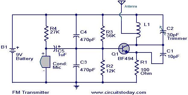
- The coil L1 can be made by winding 8 turns of 1mm thick enamel coated copper wire on a ball pen refill. The coil should be tapped at the center for connecting the antenna.
- A 30 cm wire can be used as an antenna.
- Remember! This circuit is an elementary circuit. No good performance or range is not guaranteed. Ideal for demo applications only. I got only 8 meter range with some decent sound quality.
- Battery is strictly recommended because mains powered supply may induce additional noise.
21 Comments
Assalam O Alikum friends…
I make this circuit and this circuit is run….
Many people are confuse that how to make the Inductor coil ….
its really a difficult thing to make a 1mm diameter of 8 turns of inductor….so i suggested all the members to make 4-6 turns in on a ball pen and then i hope that this circuit will we run…
Thanks …….
This circuit my project and i submit it with the same components..
Thanks for this great circuit.
I would like to know whether the wire of exact gauges is required.
Also please try to make the coil diameter more specific. ball pen refills may not be of same size every where.
Thanks in advance..
The gauge should be 18SWG and the ID of the winding should be 6mm / 1/4 inches.
sir,
what changes will be need if i replace the mic with audio input…
but at what freequency the reciever will receive the sound……….
Hi abc BF494’s pin out are different from BC548 please chech the connections.
i made it (dis ckt.) … but its not workingggg 🙁 , dunt know whyyyy
pleas send for me many projects.
Hi!
If I remove the MIC, R4, C4 and C3 and feed a stable voltage in the base of Q1, will it transmit a single sine wave of frequency determined by L1 and C2?
Thanks!
I am a beginner. don’t know how to make the coil. what do you mean by tapping at the centre.
.
Hi Mishra please refer to notes above.
Hi,
what is value for L1.
Thank you for posting this.
thanks for introducing many circuit diagrams …………
…………………….it may use full to any one who wants to make a project……………………………
Just as a guide, on what frequency range would this transmit?
Cheers,
Daniel
Hi Well 1mm is 18 AWG or 19 SWG.
yoman jst ucould tell dat 1mm wire = how many guage ???
please give some discription about this circuit
i am a technical school student. now it is summer vacation for me. so this is a practical experiment for me. so i will try this.
DON’T YOU MIND,SEND ME SOME PRACTICAL SIMPLE ELECTRONIC CIRCUITS. thanks
there are a lot of simple electronic circuit in the site itself. please look through and you will find a lot.