An RFID based Attendance System is a very interesting project which can be used in different places say in Schools to register the attendance of students and teachers, Private organizations to tabulate monthly working hours of employees and automatically calculate salary based on the number of hours registered in the office and other similar kinds of applications.
An RFID based attendance management system can be designed using different types of microcontrollers, say an 8051 series controller, an AVR, a PIC or an ARM controller. The same RFID attendance system can also be developed using popular development boards like Arduino, Raspberry Pi etc.
The choice of a microcontroller or a development board is purely based on the additional features and functionality you plan to incorporate into the system. For an example: – If you plan to export all registered data in the system into a web platform (say a cloud host) at the end of every week, it’s good not to use 8051 series controller to design such a system. Such a kind of system which communicates with the internet can be designed efficienlty (and easily) using AVR Atmega series controllers. If you are designing for hobby purpose, such a system can be easily designed using Arduino.
RFID Based Attendance System Using Arduino
In this project, we are going to build an RFID based attendance system using Arduino. An RFID based Attendance Management System is based on some simple concepts. We store a set of RFID card data in our system, say 3 or 10 RFID card data. When the person with the right RFID card (compatible to data preloaded in our program/system) come and swipes his RFID tag, his arrival time will be stored on the system. When the same person swipes his RFID tag again, the system will save it as his leaving time and add it to his total working hours.
Before we begin, please go through our tutorial on how to interface RFID Reader to Arduino and also read our tutorial on RFID based Access Control System using Arduino.
Objectives
- Display the current time and date on the LCD along with an option for menu button.
- Save the arrival and leaving time details of a user in the EEPPROM of arduino.
- Calculate & store the total working hours of each user and provide options in the menu for retrieving it.
- Provide an option for clearing data which can access only by the admin using his ID.
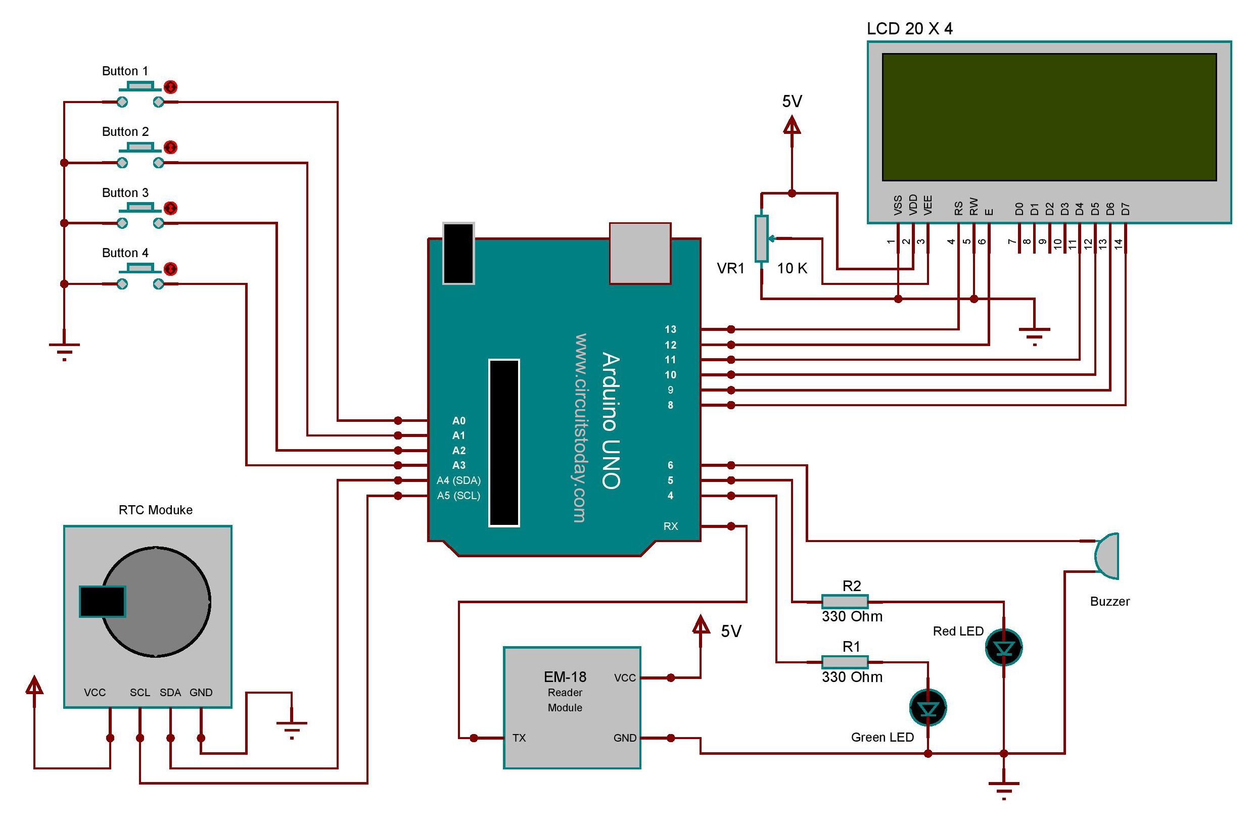
Circuit Diagram -Arduino RFID Attendance System
Project Description
The full circuit diagram for interfacing RFID module to Arduino is shown above. The unique ID code in the RFID card is read by the circuit and the name of the corresponding person will be displayed on the 20 x 4 LCD display. TX pin of the RFID module is connected to the 0th pin (RX) of arduino. The Arduino receives data from the RFID module through this channel.
Button 1,2,3,4 are used for selecting the menu and different options within the menu. The Arduino pins to which the buttons are connected are configured as “INPUT_PULLUP” within in the program. This will eliminate the use of of external pull up resistors by enabling the internal pull ups of Arduino. A buzzer and two LED indicators are also connected to the 5th,4th & 3rd pin of the Arduino respectively. The buzzer sounds upon receiving an ID code when a card is read by the circuit.
Our system uses a 20 x 4 LCD module for displaying purpose.The working and interfacing of 20×4 LCD module is similar to that of 16 x2 LCD expect that it consist of few more rows and columns. The RTC module that we use here is DS1307 IC. The RTC Module is connected to the Arduino using I2C protocol. The SCL and SDA pins are used for establishing I2C communication.
Program/Code
The libraries that we are using here are “LiquidCrystal.h”, “EEPROM.h”, “wire.h”. LiquidCrystal is for interfacing LCD module. EEPROM writing and reading are carried out using the functions provided by the “EEPROM.h” library. The “wire.h” library allows you to communicate with I2C / TWI devices(RTC Module).The address of the I2C device is mentioned on the beginning of the program. There are both 7- and 8-bit versions of I2C addresses. 7 bits identify the device, and the eighth bit determines if it’s being written to or read from.
The Wire library, which is used for I2C bus communication, followed by defining the bus address for the RTC as 0x68. These are followed by two functions that convert decimal numbers to BCD (binary-coded decimal) and vice versa. These are necessary because the RTC ICs work in BCD not decimal. The function setTime() is used to set the clock. Using it is very simple to insert the values from year down to second, and the RTC will start from that time. Once you have run the function once it’s wise to prefix it with // and upload your code again, so it will not reset the time once the power has been cycled or microcontroller reset. Reading the time from your RTC IC is just as simple, in fac, the process can be followed neatly inside the function displayTime().
Two pointer arrays are declared at the beginning which contains the RFID codes and names of the persons. The name and ID code of every staff should be enrolled in this array on the programming time. When a person swipes his RFID card, the controller will receive a unique ID code at its RX pin. The controller will compare the received ID with the previously stored codes in the above mentioned array. If the received ID is equal to any of the ID stored in the program, the name of the person will be displayed on the LCD and the arrival time will be stored on the EEPROM of the controller.
A flag is then host inside the program to point out the presence of that person. When the same person swipes his ID again, the controller will assume that the person is leaving ( by checking the corresponding flag bit) and save that time as his leaving time. The working hours is then calculated using the arrival and leaving time. It is then added to the total working hours and stored in the EEPROM. The controller will automatically clear yesterday’s data at everyday morning(8.30 AM). The details about the total working hours of staffs can be cleared only by the admin. An option named “view all” is included in the menu which shows the total working hours of each staff from the last time of reset. Option “ view attendance” will give the arrival and leaving time of staffs present on that day. Program include the details of 10 staffs. You can make the program shorter by cutting down the number of staffs.
Thus we finished learning RFID based attendance system using Arduino. Output photographs follows!
3 Comments
The attached program code for the RFID Based Attendance System failed to open when downloaded. Am using Arduino 1.8.1. Please any help will be appreciated. Thanks for the tutorials.
Which software is used to simulate the above design?
This article on Arduino based projects is very useful and they are clearly defined. I highly appreciate the great service provided by your site
My Best Regards!
Jayantha Rathnayake