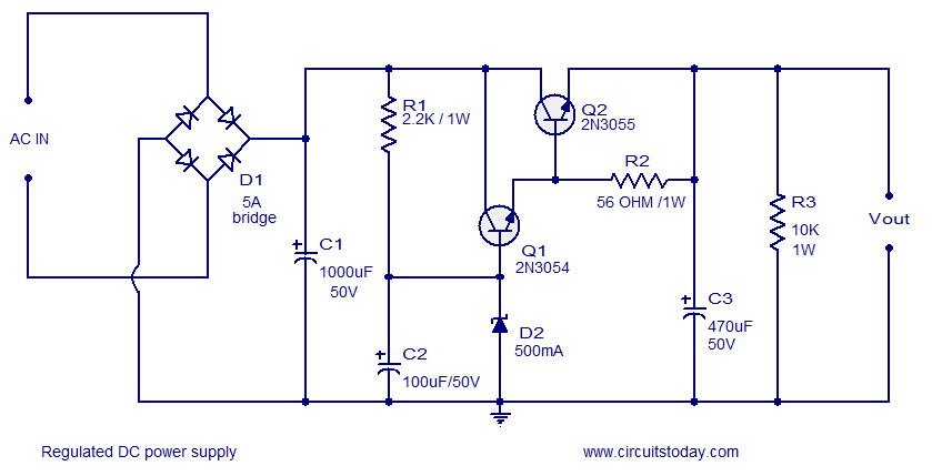
Regulated DC Power Supply using transistors.
A low ripple regulated DC power supply designed based on transistors is shown here. Such transistor voltage regulators are suitable for application where high output current is required. Conventional integrated series regulators like 7805 can only deliver up to 1A. Additional series pass transistors have to be added to the 7805 based regulator circuit for improving their current capacity.
Description.
The circuit shown below is a basic series voltage regulator based on transistors. Transistor Q1 (2N 3054) and Q2 (2N 3055) form a darlington pair. Resistor R1 provides the base current for Q1 and also keeps the zener diode D2 in the active region. The overall working of the circuit can be demonstrated by explaining two situations.
- When the input voltage (output of the rectifier section) increases, the output voltage of the regulator (Vout) also increases. This increase in Vout decreases the base emitter voltage of Q2 because the zener diode D2 is operating in the breakdown region and the voltage across it is unchangeable. This decrease in VBE increases the collector emitter resistance of Q2 and so the output voltage (Vout) gets reduced accordingly.
- When the output load increases, the output voltage (Vout) gets reduced. This decrease of output voltage (Vout) makes VBE of Q2 to decrease. This reduces the collector emitter resistance of Q2 and so the output voltage gets increased accordingly.
Circuit diagram.

Notes.
- If 5A bridge is not available, then make one using 6A6 diodes.
- Transistor Q2 requires a heat sink.
- An optional 5A fuse can be added in series to the output.
- Breakdown voltage of the zener diode D2 must be chosen according to the output voltage you need, and it is according to the equation, Vout = Vz – 0.7.

19 Comments
hi sir… can u tell me..how to construct an 6 volt dc regulated power supply…i wants its clear explanation of components used on it…and how to construct it..i need its circuit also.plz help me sir
hii ,
does it effect the output if we use other transistors instead of 2N 3055 ,2N 3054
i had used tip 142 nd tip 122 ????????
is there any future scope of this circuit ??
Please provide “Regulated AC Power supply” circuit diagram and explanation if possible..
can we use this circuit if the peak input voltage is 20-25V
THis is how Power Supplies were designed before we had LM317 7812,LM350,,,,,,,,,,,,,,Still a GREAT DESIGN,,,Thanks!!!
Hi friends The capacitor shown are rated for 50volts hence the cannot be more than 35volts. hence the transformer has to be rated for 24volts AC. The output cannot be greater than 30volts. The current can be around 2 to 3 amps.
as it showes the ac in should be more than 35 volt
this is the requlated crt can be used from 18 Ac up to 240 vac denpened on the diode and capcitor volrage rate
so ransfromer can be used for step down the repuired ac voltage
Use a Heat Sink for the 2N3055,, Then it shouldn’t get HOT!!!
Hi KE730 in series regulators when you use it at very low voltage at max current, with high voltage input the series pass transistor will get heated up, hence you have to use a good heat sink.
D2 should have been shown as 500mw zener of voltage rating equal to, output voltage required plus 1.4 volts. Vout = Vz – 1.4 volts, since two base emitter junctions are involved. By connecting 2.2k 3watt wire wound potentiometer in parallel with the zener diode and connecting the slider of the potentiometer to base of Q1 base will make it a simple variable bench supply, which is still in service with me.
I think 2N3055 will very HOT….
I like your Design!!!!! You’re using my Favorite All Time power Transistor,,,,,The 2N3055!!
Hi Mark you are correct it is not included you can use a simple fast acting fuse in the output as indicated in the notes. you can use the following circuits R2 and Q2 in the above circuit suitably calculationg R2 value as 0.7 / the current limit required.
There is not short circuits protection
Then why you not show Transformer,? ,, most who come here, not here because they already know things, they here to learn, don’t be halfwit,, do complete schematic so not to confuse us. YOU the one who show way, you leader, teacher, do good job or quit
reply to nireekshith
this is not a transformer less power supply.
transformers secondary has to be connected to the input of the bridge.
ratings of the transformer depends on what voltage/current you need at the regulator output.
Is this regulated dc power supply circuit with out a transformer……….?, why transformer had not been used in this…….?
reply to nireekshith
this is not a transformer less power supply.
transformers secondary has to be connected to the input of the bridge.
ratings of the transformer depends on what voltage/current you need at the regulator output.