Designing a Real Time Clock using Dot Matrix Display on Proteus
Objective -Display Time on an 8X32 Dot matrix Display
In this article, a Real Time Clock RTC DS 1307 is interfaced with a microcontroller and the time is displayed on a Dot matrix display. The circuit is simulated using the Proteus software. We shall discuss the project in two parts, one is interfacing the Dot matrix display and the other is interfacing the RTC DS 1307. Any RTC IC, for example, DS 3232 comes with an integrated crystal with which alarms can be interfaced.
This article explains the programming part using the software ‘mikro C PRO for AVR’ in a progressive way. Logic is developed step by step so that by following the article, one can design displays of different sizes and formats. Let’s discuss the dot matrix displays first. Showing text or characters on a matrix display is done by refreshing the display with data frames. Now, we will discuss column refreshing. For this purpose, data frames for the columns are gathered and refreshed.
Selection of Dot matrix Display Array
32 X 8 Array contains 8-Rows and 32-Columns. This is selected because we have to display time with seconds’ resolution and it contains 6 digits. Each digit is framed as a 5 X 7 Matrix i.e.., 5-Columns and 7-Rows. So, for six digits we need 5*6=30 columns and two columns for separating hours, minutes and seconds. From the displays readily available as a module, 4*8X8 LED Matrix displays are sufficient. However, we can change the display array according to our requirements by making suitable corrections in the programming part.
Framing the characters
Now, let’s frame the digits as a 5X7 Matrix. For this purpose, we need to declare a two-dimensional array of ‘char’ type for 10 digits. Below image shows the framing of digit ‘0’ for a Column Common Cathode type of module which means that columns are enabled by giving low signal and corresponding row LEDs are enabled with high signal
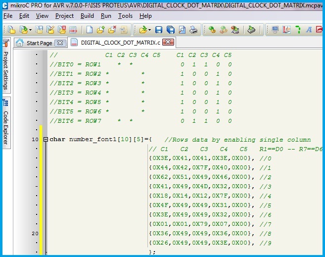
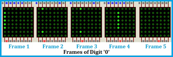
From the above image, every dot in the digit is considered as High i.e.., logic 1. As there are 5-Columns, for every single column, the row LEDs which should glow is stored in the array. Thus we need 5-bytes for every digit. The font or style is of our choice. The style can be of segment type also. We should frame the digit according to the shape. Similarly, other digits are also framed. Below image shows frames of digit ‘0’ of a Column common anode type as it is readily available in proteus. Just by negating the data, the framed characters can be interchanged.
As the digits are framed, it’s time to display them. To display the digits on the matrix arrays, 5-Pins to control individual columns and 7-Pins to control rows are required in this case. The program flow is like this, Enable column-1 and issue corresponding rows data to the rows. Wait for a few milliseconds and disable the column-1. Now, remove the rows data, Enable column-2 and issue rows data of column-2. Repeat the previous steps continuously as a loop to show the digit.
For a single digit, it is feasible to control with a single microcontroller. But if a number of matrices are combined to form an array, the above circuit is modified, leaving the same program flow. To reduce the column pins, Column-1 of all the 8X8 matrices are connected together to form a single node and like vice the remaining columns. So, only 8-Pins are required to control all the columns of the array.
As discussed already, columns are just refreshed in a particular and single sequence which is shifting HIGH Signal from one column to the next column. For this purpose a decade counter IC can be used. Now we are using the 8X8 Matrix and so we have to control 8-Columns. By ‘Resetting’ the decade counter with 9th output, we can achieve the required sequence. The Microcontroller has to send the clock signal through one of its I/O Pins to the decade counter and one more pin is required to Master Reset the counter while starting the display to avoid data corruption. So, now we have reduced the column control pins from 5 pins to 2 pins. This is applicable to refresh arrays up to 10-Columns (In case if you are designing your display panel without using ready-made modules).
Serial transmission of data from microcontroller
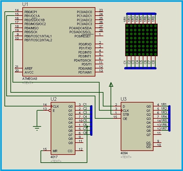
Now, let’s reduce the row controlling pins. For this purpose, we are using Serial-In, Serial-Out and Parallel-Out registers with Load/Store and Output Enable inputs. The microcontroller should have the SPI-Serial Peripheral Interface feature. The Rows Data from the microcontroller is shifted serially into these registers for each frame of the entire display board. Then the data is loaded at the parallel output of these registers by issuing Load and Output Enable signal from the microcontroller. In this project we have enabled the load/STB pin permanently by connecting it to the Vcc. So, for row data transmission we need two pins for serial transmission and two pins for Load and Enable signals. One register is required for one matrix. So, we have to increase the matrices and registers as a pair to increase the size of the array. Below is the modified circuit diagram.
The circuit building procedure and SPI enabling code is shown in the following video.
Building the Circuit – Demonstration
The program flow and the simulation output is presented in the following video. Up to now, we have used only 5-columns of the 8X8 matrix to show single digit.
Simulation Output
Do not assume these outputs as the final output. Our aim is to display the time on the matrix array which contains six digits. In order to display these many characters, we have to modify our circuit by extending the matrix display modules and shift registers.
Modifying the circuit
Framing the text
It is difficult to show these six digits with the above program format, it is better to group all the row data for each column into single variable. Suppose that, we have to show the digits 0 to 5. Now we have to form an array in which the row data of all these digits are stored one after the other. To shorten the explanation, let’s frame the digits as if we are showing the time. For this purpose, we have to define an array named ‘time’ of char type and this contains the actual time that we are going to read from the Real Time Clock. As our array contains 32 columns, the data array has to store 32 bytes.
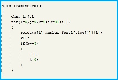
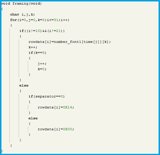
Now we have stored the rows data for individual columns in a single array. As we have to display the time, we have to separate hours, minutes and seconds. So, we have to insert these gaps or empty data bytes in between the array framed just now.
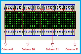
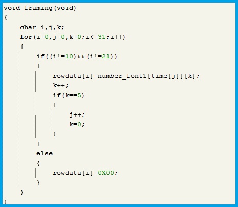
By counting the digits in terms of columns, we have separators at 10th and 21st columns. The modified code to include separators is shown below.
Shifting data from microcontroller to the shift registers
It’s time to display the characters. We have to send the data stored in the row data array frame by frame from the microcontroller to the shift registers. As there are 8-Columns for each matrix and we have combined unique columns of all the matrix modules, there are 8-Frames. Below is an example of frame wise display.
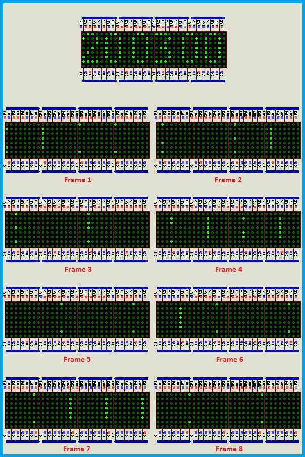
From the above image, it is clear that we have to send the data according to frames. In the first frame, data corresponding to Column-1 of all the matrices is sent. As we are issuing the data through the serial shifting registers, data corresponding to column-1 of the 4th matrix is sent first and then 3rd matrix, 2nd matrix and then finally 1st matrix. Below is the One-One relation among the Columns and the previously framed rows data array.
Column Row Relationship - Matrix Display
| S.No. | Column in terms of matrices | Rows data array address |
|---|---|---|
| 1. | Matrix 1- Column 1 (M1 C1) | 0 |
| 2. | M1 C2 | 1 |
| 3. | M1 C3 | 2 |
| 4. | M1 C4 | 3 |
| 5. | M1 C5 | 4 |
| 6. | M1 C6 | 5 |
| 7. | M1 C7 | 6 |
| 8. | M1 C8 | 7 |
| 9. | M2 C1 | 8 |
| 10. | M2 C2 | 9 |
| 11. | M2 C3 | 10 |
| 12. | M2 C4 | 11 |
| 13. | M2 C5 | 12 |
| 14. | M2 C6 | 13 |
| 15. | M2 C7 | 14 |
| 16. | M2 C8 | 15 |
| 17. | M3 C1 | 16 |
| 18. | M3 C2 | 17 |
| 19. | M3 C3 | 18 |
| 20. | M3 C4 | 19 |
| 21. | M3 C5 | 20 |
| 22. | M3 C6 | 21 |
| 23. | M3 C7 | 22 |
| 24. | M3 C8 | 23 |
| 25. | M4 C1 | 24 |
| 26. | M4 C2 | 25 |
| 27. | M4 C3 | 26 |
| 28. | M4 C4 | 27 |
| 29. | M4 C5 | 28 |
| 30. | M4 C6 | 29 |
| 31. | M4 C7 | 30 |
| 32. | M4 C8 | 31 |
The program logic for sending the data according to discussed format is shown below. Before starting while loop we have to call the ‘framing’ function.
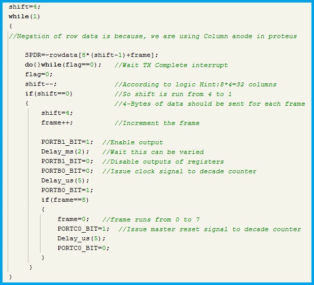
By default, we have pre-defined the time as 12 00 00 by issuing respective values in the time array. The sequence of the time array is as follows, ‘time[0]’ == ten hours and ‘time[5]’ == seconds. The simulation output is shown below.
Interfacing the Real Time Clock IC
By now, we have completed interfacing dot matrix display array. We shall now discuss the second part, which is about interfacing the RTC DS 1307/ DS 3232 IC and then read the time from it. This requires TWI–Two Wire serial Interface feature in the microcontroller. We are using ATMEGA 8 microcontroller. As per the data sheet, the program code for data transmission and reception is as follows. We have to read data from the RTC IC and shift them to our previously declared ‘time’ registers. A square wave of 1Hz frequency is generated from the RTC IC through suitable register settings. This square wave is used as an external interrupt source to the microcontroller and thus time registers are updated every second. Below is the code for the procedure discussed.
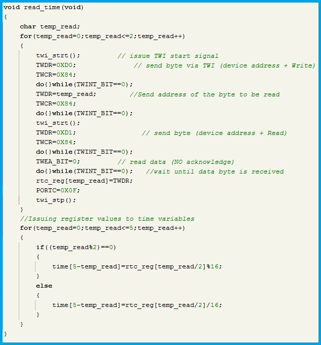
This read operation is performed every second. The read function is called in the interrupt sub-routine of the External interrupt which is activated by the 1 Hz square wave input. The blank separator column can be changed to the conventional blinking dots by the following snippet. For every second, the data corresponding to the separator column is changed from the blank data to the dots in the interrupt sub-routine of square wave input.
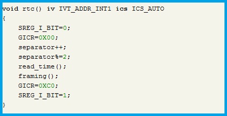
Based on the separator value which is either ‘0’ or ‘1’, the row data array of these two columns is changed along with the time in the framing function. Below is the code for this.
Below is the simulation output of the project coded till now.
Editing the time
By now we have interfaced dot matrix displays and real time clock. The obtained output at this state does not provide the user to edit the time. As a final step let’s code for editing the time. For this purpose, we use 3 Push buttons for set/change, shift between digits and adjust the selected digit. The external interrupt INT0 of the microcontroller is used for editing the time. The circuit is developed in such a way that, operating any of the push buttons will generate an interrupt. Thus, by reading the actual button that is operated in the interrupt sub-routine, we take an appropriate action to change the time. Below is the circuit diagram.
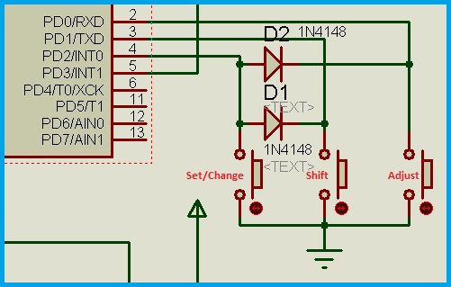
The program logic for setting the time is provided in the program file. To indicate the digit under selection, the display is framed up to the selected digit only. For this purpose, a function called ‘set_framing’ is defined and called during editing.
Simulation output with editing feature
While hardware implementation, it is better to use drivers for columns, as decade counter alone cannot drive the whole current. If column cathode type modules are used, remove the negation while loading SPDR with row data and NPN transistors can be used for driving the columns by driving their bases with the outputs of the decade counter.
Downloads
Download – C Program File and Hex Binary File
So we finished our tutorial on building a real time clock on Proteus enviornment using Dot matrix LED display.
Comments are closed.