In this article we explain how to do PWM (Pulse Width Modulation) control using arduino. If you are new to electronics, we have a detailed article explaining pulse width modulation. We have explained PWM in this tutorial using 2 examples which will help you learn how to control LED brightness using PWM and how to control DC motor speed using PWM.
PWM control using arduino.
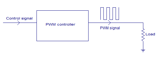
PWM control is a very commonly used method for controlling the power across loads. This method is very easy to implement and has high efficiency. PWM signal is essentially a high frequency square wave ( typically greater than 1KHz). The duty cycle of this square wave is varied in order to vary the power supplied to the load. Duty cycle is usually stated in percentage and it can be expressed using the equation : % Duty cycle = (TON/(TON + TOFF)) *100. Where TON is the time for which the square wave is high and TOFF is the time for which the square wave is low.When duty cycle is increased the power dropped across the load increases and when duty cycle is reduced, power across the load decreases. The block diagram of a typical PWM power controller scheme is shown below.
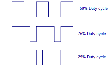
Control signal is what we give to the PWM controller as the input. It might be an analog or digital signal according to the design of the PWM controller. The control signal contains information on how much power has to be applied to the load. The PWM controller accepts the control signal and adjusts the duty cycle of the PWM signal according to the requirements. PWM waves with various duty cycle are shown in the figure below.In the above wave forms you can see that the frequency is same but ON time and OFF time are different.Two applications of PWM control using arduino is shown here. Controlling the LED brightness using arduino and motor speed control using arduino.
LED brightness control using arduino.
This one could be the simplest example of PWM control using arduino. Here the brightness of an LED can be controlled using a potentiometer. The circuit diagram is shown below.
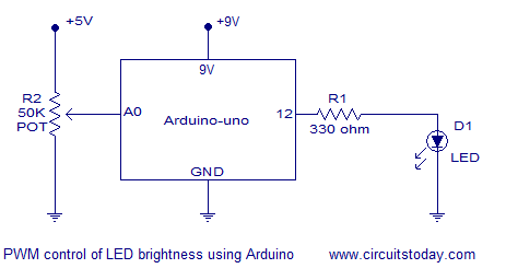 In the circuit, the slider of the 50K potentiometer is connected to analog input pin A0 of the arduino. The LED is connected at digital pin 12 of the arduino. R1 is a current limiting resistor. The working of the program is very simple. Arduino reads the voltage at the analog input pin A0 (slider of the POT). Necessary calculations are done using this reading and the duty cycle is adjusted according to it. The step-by-step working is noted in the program below.
Program.
int pwm = 12; // assigns pin 12 to variable pwm
int pot = A0; // assigns analog input A0 to variable pot
int t1 = 0;   // declares variable t1
int t2 = 0;   // declares variable t2
void setup()  // setup loop
{
  pinMode(pwm, OUTPUT); // declares pin 12 as output
  pinMode(pot, INPUT);  // declares pin A0 as input
}
void loop()
{
  t2= analogRead(pot); // reads the voltage at A0 and saves in t2
  t1= 1000-t2;         // subtracts t2 from 1000 ans saves the result in t1
  digitalWrite(pwm, HIGH); // sets pin 12 HIGH
  delayMicroseconds(t1);   // waits for t1 uS (high time)
  digitalWrite(pwm, LOW);  // sets pin 12 LOW
  delayMicroseconds(t2);   // waits for t2 uS (low time)
}
Example.
The following example helps you to understand the stuff better.
Suppose the slider of the potentiometer is adjusted so that the voltage at its slider is 3V. Since the slider terminal is connected to A0 pin, the voltage at A0 pin will be also 3V. analogRead function in arduino reads the voltage (between 0 to 5V) at the analog input pin,converts it in to a digital value between 0 and 1023 and stores it in a variable.
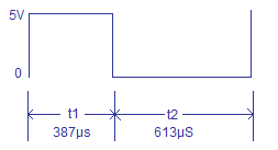
Since the analog input voltage here is 3 volts the digital reading will be 3/(5/1023) which is equal to 613. This 613 will be saved to variable t2 (low time). Then t2 is subtracted from 1000 and the result which is 387 is stored in variable t1 (high time). Then digital pin will be switched on for t1 uS and switched off for t2 uS and the cycle is repeated. The result will be a square wave with high time = 387 uS and low time = 613 uS and the time period will be always 1000uS. The duty cycle of this wave form will be (387/(387+613))*100 which is equal to 38.7%. The wave form will look something like what is shown below.
Motor speed control using arduino.
Circuit diagram of DC motor speed control using arduino is shown in the figure below. The working principle and program of this circuit is same as that of the LED brightness control. Only difference is that and additional motor driver circuit using a transistor is included in the circuit. Each digital pin of the arduino can sink or source only 40mA. DC motors usually consume much more than this and it is not safe to directly connect a heavy load to the digital pin.
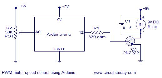 In the circuit diagram, slider of the potentiometer is connected to analog input pin A0 of arduino. Resistor R1 limits the base current of the transistor Q1. Motor is connected as collector load to the transistor. Capacitor C1 by-passes voltage spikes and noises produced by the motor. This filter capacitor is very essential and if it is not there the circuit may not work properly.
Program.
int pwm = 12; // assigns pin 12 to variable pwm
int pot = A0; // assigns analog input A0 to variable pot
int t1 = 0;   // declares variable t1
int t2 = 0;   // declares variable t2
void setup()  // setup loop
{
  pinMode(pwm, OUTPUT); // declares pin 12 as output
  pinMode(pot, INPUT);  // declares pin A0 as input
}
void loop()
{
  t2= analogRead(pot); // reads the voltage at A0 and saves in t2
  t1= 1000-t2;         // subtracts t2 from 1000 ans saves the result in t1
  digitalWrite(pwm, HIGH); // sets pin 12 HIGH
  delayMicroseconds(t1);   // waits for t1 uS (high time)
  digitalWrite(pwm, LOW);  // sets pin 12 LOW
  delayMicroseconds(t2);   // waits for t2 uS (low time)
}
Notes.
- In both circuits shown above the arduino is supposed to be powered through the 9V external power input jack.
- +5V supply for the potentiometer can be taken from the 5V regulator output on the arduino board.
- The DC motor I used while testing was rated 9V/100mA.
- The LED I used while testing was a general purpose 4mm bright green LED.
- The maximum collector current 2N2222 can handle is 800mA. Keep this in mind while selecting the motor.
- Be very careful while handling the arduino board. Any wrong connections might damage the board

6 Comments
pls can u explain why 1000 has been taken chosen as the upper limit for subtracting , supposing the pot is at full it is 5v ie it will become 1023 so 1000 – 1023 = -23 will this not become an error
how should i connect this for AC motor/ fan
Hi,
This basic program and basic circuit design is good and also helpful,
Thanks
Hello,
I have tried this circuit and I find that the motor makes an audible noise because of the ~500Hz frequency of the PWM, I have tried changing the timer prescaler but It ends up putting the analogRead out of timing too.
Any ideas how to remove the audible noise and keep the analogIn?
So if i were to modify the motor speed control using arduino to run 2x motors (in parallel) that ran @ 12v .4A on one pwm channel, what would the capacitor rating and transistor rating have to be? would an NTE293 npn transistor be sufficent? And if so, does R1 have to be changed at all?
My perticular application is to run 6 pwm channels controlling 2 computer fans per channel for a total of 57.6W with the above motor ratings. space is limited so i will be using the arduino micro. I would like to have a little give though with the transistor, so that if I later get a fan with a slightly higher wattage, it wont burn out the system; hence want to switch from the 800mA limit on the 2n2222a.
I am not the most knowledgable when it comes to the maths involved, so please forgive me if it completely screwed the equasions and limits. I hope my intentions were made clear and if you could help, that would be much appericated.
Thanks, Nick
Greetings Sirs
we have plane to develop an Inveter using PWM principle, please assist me to develop it with your much needed ideas.
regards
leyart silva