Arrangement of LED’s
Consider an 8X8 matrix display, which means it contains 8 LED’s in each row and 8 such rows are used to form the matrix. Thus, it contains 64 LED’s (8*8).It is hardly practical to operate these 64 LED’s individually using any kind of digital circuits or microcontroller circuits. Hence, multiplexing is done to interface these LED’s with minimum number of pins. Typically, an 8X8 matrix display can be interfaced with 16 pins.
Similar to a seven segment display, in which the seven segments and the decimal point have common node, either cathodes or anodes of the LED’s are made common, matrix displays also have a common node for each row and column.
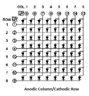
Either, (i) anodes of LED’s belonging to one column are made common and cathodes of LED’s belonging to one row are made common => Column Anode/Row Cathode
Or
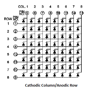
(ii) Cathodes of LEDs belonging to one column are made common and anodes of LEDs belonging to one row are made common => Column Cathode/Row Anode
This column and row perception is according to the physical placement of the display as per the manufacturer. By changing the physical placement of display in the circuit, rows and columns will be different from the pin configuration mentioned by the manufacturer.
Pin configurations of Matrix Display in Proteus
Proteus contain 8X8 and 5X7 Dot matrix displays of single colour as far as 7.7 version is concerned, although 5X8,16X16 so on.., matrix displays with bi-colour and RGB colours are available in market.
Dot matrix displays are found under the category of Displays in Proteus. The 8X8 matrix display provided in Proteus can be used as a column anode display which means that anodes of LEDs in a column are made common. To select a matrix display
Step 1: Select component mode
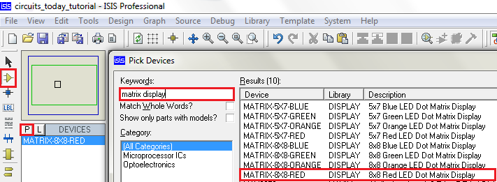
Step 2: Click on Pick devices ‘P’ .
Step 3: Type matrix displays in text box
Step 4: Select desired display
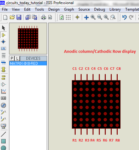
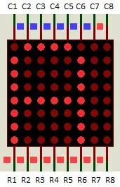
The schematic symbol of 8X8 matrix has Column pins on the top and Row pins at the bottom in default orientation/placement of the component in the work space.
Using Matrix Display
In order to display a character or shape on a matrix display, the character is fragmented into several frames such that, by playing/blending these frames sequentially at a speed, faster than that human brain can perceive, the character appears to be displayed continuously (Persistence Of Vision). This is similar to ‘GIF format’. Fragmentation can be done along the column or along the row.
Consider a Column Anode/Row Cathode matrix display, to display a character alphabet ‘A’, as shown in the image below:
This character can be fragmented into columns to get frames.
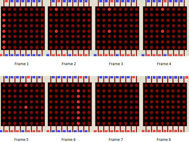
Frame 1 shows column 1 of the character ‘A’. This is done by latching Column 1 pin to +5V and 0V to remaining column pins. Now, the required rows are enabled by latching them to 0V and remaining rows are latched to +5V. Similarly, remaining columns are enabled and corresponding rows are enabled for each column respectively.
In each frame only one column is enabled by connecting it to positive voltage (+5V) and 0V(GND) is connected to the corresponding rows which should glow for the enabled column. Remember that this is a Column Anode/Row Cathode display. The connections are vice versa for a Column Cathode/Row Anode display.
Displaying Character at a Slower Refresh Rate
Similarly, rows can be enabled individually and respective columns are enabled for each row i.e.., fragmenting along rows. This entire switching sequence is done by microcontroller. The programming can be done in numerous ways depending on the programmer. Refreshing of the frames is generally done at 60Hz in LED displays, but this is variable.
Comments are closed.