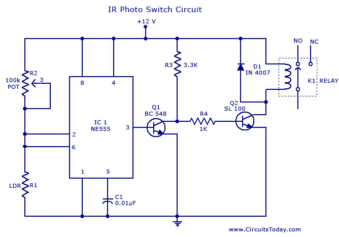
In this project, We’re building a Photo Switch Circuit using 555 IC. If you’re not familiar with the term ‘photo switch’ – this is nothing but a light-activated switch. The switch will turn ON/OFF based on light intensity. We’ve designed this photo switch circuit using simple & popular components. The heart of this circuit is the very popular NE/SE 555 IC – which is a timer IC almost everyone is familiar with. If you’re new to 555 IC, you may begin reading more about 555 in our article – 555 IC The Basics.
This circuit is very simple and easy to make. The light intensity is sensed using an LDR and the desired intensity can be set by adjusting the potentiometer. Switching is handled using 555 IC and the two transistors. The output is actuated using the relay mechanism.
Description
This is a simple photo switch suitable for home and industrial purposes.The circuit switches on a relay when the light intensity falling on the sensor crosses the set limit.
The circuit is based on a NE 555 and two transistors for driving the relay. The resistor R1 is adjusted in such a way that under normal condition the voltage across the LDR is less than 1/3 the supply voltage. In this condition output of IC is high . This makes transistor Q1 on . Transistor Q2’s base is connected to the collector of Q1.So Q2 will be off keeping the relay de-energized. When light falls the voltage across LDR rises above 2/3 Vcc. This makes the output of IC go high making the relay energized. The result we get a relay that operates according to the intensity of light falling on the LDR.
Notes.
Assemble the circuit on a good quality PCB or common board.
To set up the circuit switch on the power supply, connect a multimeter across LDR and adjust R1 so that voltage across LDR is just below 1/3 supply voltage. Ensure that relay is off in this condition. If not reduce the voltage across LDR further more by adjusting R1 to make relay off.
Now cover the top of LDR using a black paper and see the relay gets activated. If not, make further adjustments with R1. Nothing to care about some trial and error you will get the correct setpoint of R1 where the circuit works. This circuit is nothing great, but some simple basics. I have tested this and got good results. So no problem. Just proceed.
If there is some chattering in the relay, that may be because off the difference between the turning on and turning off voltages. This can be avoided by connecting a resistor whose value is equal to 1/2 the resistance of LDR at the illuminated condition.
Circuit Diagram and Parts List.


21 Comments
I want to make the auto Stick for blind people. Will U pl help me to pass circuit for electronics auto road detector for blind people !!!
What is the equil of Q2 this circuit?
I used LM324 instead of 555 timer IC
12 volt 50 to 100mA relay ( 240 or 120 ohms) with single chaneover contact with a rating of 230 volt 5 amps.
what are the relay specifications?
what we want to make changes for make ir sensor as a red led sensor??
night light operation and working application adv disadv
Hi Botsha you can use any circuit diagram published for personal use. you should not exploit it commercially.
This is a simple dark switch. when the suurounding lights go dark this can swich on lights. can be used as dusk light. during sun set it switch on and at dawn it will switch off.
i want to use your work for a university project here in nigeria if you permit. that is the circuitry and other related sentences to critisize a related work. what i found in your work says it all. am i permitted? if possible feed me with more on technical electrical theory of operation.
sir how to contruct a photo switch?
Bob,
Don’t know if you’re still interested, but if your camera had a constant buffer, ie. recording constantly, perhaps the light sensitive rig could just tell the camera to keep the last couple seconds worth of images. Then the response time of the circuit wouldn’t be so crucial.
thank you for the help !..God blessed us!
Good day Sir! what is the replacement of Q1 and Q2 because in the Philippines is not available?. thank you?
Q1 can be replaced by any low power NPN transistor.Few eligible candidates are BC547,2N2222,BC107,BF494 etc.
Q2 can be replaced by any medium power NPN transistor.Few eligible candidates are BD135, BD139, TIP31 etc.
If a medium power NPN transitor is not available then use a low power NPN transistor on its place.The will not be much problem.
These transistors can be easily found inside discarded electronic equipments like telephone, radio, tape recorder, Tv , VCR, inverter etc.
im doing a project on da above ckt,but insted of NE 555 we used an IC LM311
This circuit might fit a need. Let me explain. I’d like to trigger a camera by using this or similar circuit to close a circuit. The light source would be lightning, so the reaction time would need to be quite fast. And that bring this post. I can rig the camera to react quite fast by bypassing all the auto functions and by lifting the mirror before the shutter is triggered, but I don’t know if this circuit would be up to the task. A lightning flash can last as long as a fifth of a second.
Can someone advise me?
Thanks,
Bob